|
|||||||


| Rotary Tech - General Rotary Engine related tech section.. Tech section for general Rotary Engine... This includes, building 12As, 13Bs, 20Bs, Renesis, etc... |
 |
|
|
Thread Tools | Display Modes |
|
|||||||
| Rotary Tech - General Rotary Engine related tech section.. Tech section for general Rotary Engine... This includes, building 12As, 13Bs, 20Bs, Renesis, etc... |
|
|
|
Thread Tools | Display Modes |
 05-23-2011, 03:44 PM
|
#16 | |
|
Rotary Fanatic

Join Date: Feb 2008
Location: Slidell, LA
Posts: 191
Rep Power: 18  |
Quote:
Barry |
|

|

|
|
05-23-2011, 05:47 PM
|
#17 | ||||||
|
The quest for more torque

Join Date: Sep 2008
Location: Sheboygan, Wisconsin
Posts: 855
Rep Power: 18 |
Quote:
Quote:
Quote:
Quote:
Quote:
Quote:
__________________
1986 GXL ('87 4-port NA - Haltech E8, LS2 Coils. Defined Autoworks Headers, Dual 2.5" Exhaust (Dual Superflow, dBX mufflers) 1991 Coupe (KYB AGX Shocks, Eibach lowering springs, RB exhaust, Stock and Automatic) |
||||||
|
|
|
|
05-23-2011, 06:01 PM
|
#18 | |
|
The quest for more torque
Join Date: Sep 2008
Location: Sheboygan, Wisconsin
Posts: 855
Rep Power: 18 |
Quote:
I re-used that seal. I have over 2500 miles on the engine since the failure and have had no issues. Stock water pump, stock radiator (a lot of fins are rotted out, I am replacing it). I read this thread earlier and I found the tell-tale pattern on my housings, so I figured that beveling the edges was a good idea that may keep me from losing an engine. It survived 3000+ miles on the street just fine, but didn't survive the dyno run. I should have backed out of the throttle and had the dyno turn the loading down, My coolant temp was about 125 C when the seal went. I went to the dyno since then and had no issues (with the temp under 115 C) I think that the spark plug boss grows too much relative to the unsupported housing around it. I have considered welding a brace in (parallel with the coolant flow) to keep the surrounding housing growing at a similar rate to the spark plug hole (although the spark plug hole has threads in it). I like racing beat's idea - if I had this information before I rebuilt the engine, I probably would have done that.
__________________
1986 GXL ('87 4-port NA - Haltech E8, LS2 Coils. Defined Autoworks Headers, Dual 2.5" Exhaust (Dual Superflow, dBX mufflers) 1991 Coupe (KYB AGX Shocks, Eibach lowering springs, RB exhaust, Stock and Automatic) |
|
|
|
|
|
05-23-2011, 07:58 PM
|
#19 | ||||||
|
RCC Loves Me Not You

Join Date: Jul 2008
Location: Influx.
Posts: 2,113
Rep Power: 20 |
I think you're missing what I'm saying.
Quote:
Quote:
Quote:
Quote:
Quote:
Quote:
__________________
The Official FC Radiator Thread My Project Thread: Cerberus CCVT Virginia Rotary Group |
||||||
|
|
|
|
05-23-2011, 08:12 PM
|
#20 | |
|
RCC Loves Me Not You
Join Date: Jul 2008
Location: Influx.
Posts: 2,113
Rep Power: 20 |
Quote:
__________________
The Official FC Radiator Thread My Project Thread: Cerberus CCVT Virginia Rotary Group Last edited by Barry Bordes; 05-24-2011 at 06:38 AM. |
|
|
|
|
|
05-24-2011, 06:53 AM
|
#21 | |
|
Rotary Fanatic
Join Date: Feb 2008
Location: Slidell, LA
Posts: 191
Rep Power: 18 |
Quote:
It didnt seem to help much to alleviate the growth problem as I had hoped. The next set of mods included severed fins and larger balanced passages. |
|
|
|
|
|
05-24-2011, 07:49 AM
|
#22 |
|
Can't.Make.Up.My.Mind.
Join Date: May 2009
Location: Murfreesboro, TN
Posts: 1,377
Rep Power: 18 |
Barry,
You said you were using reliability mods.. What mods exactly were you using? Ported? etc, etc, Just curious 
__________________
'90 GTUs Stay up to date with my photography '06 Toyota Highlander Hybrid '10 Toyota Prius "Initial Success or Total Failure" |
|
|
|
|
05-24-2011, 08:05 AM
|
#23 |
|
Test Whore - Admin

Join Date: Mar 2008
Location: Right Behind you son
Posts: 4,581
Rep Power: 10 |
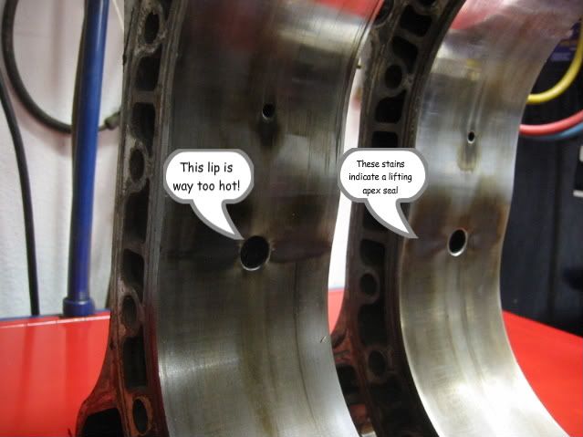
It seems to me that the stain is in line perfectly with the fin. It appears to me that the fin has kept that area from growing. Effectively retracting it as the rest of the housing grows. Looking at the 16x and the renni, they seem to aleviate some of this material. I'm wondering if this is in an attempt to not contain it, but to let it grow a the same rate. Thoughts?
__________________
-The Angry Stig- DGRR 2009, 2011, 2012 & 2013 - Best FC DEALS GAP!! WOOHOOOO!!!!! 2015 Audi S4 - Samantha - Zero Brap S4 2004 RX8 - Jocelyn - 196rwhp, 19mpg fuel to noise converter 2000 Jeep Cherokee Sport - Wifey mobile - Now with 2.5" OME lift and 30" BFG AT KO's! So it begins 1998 Jeep Cherokee - 5 spd, 4" lift, 33" BFG's - Rotary Tow Vehicle 1988 'Vert - In progress 1988 FC Coupe - Gretchen -The attention whore BEAST! I'm a sick individual, what's wrong with you? I'm pure Evil I'm still insane, in the best possible way. I think Brian's idea of romance is using lube. Your rage caused the meteor strike in Russia. The Antichrist would be proud of his minion. You win with your thread. Most everything It's a truck with a steel gate on the back. Just a statement of fact Motec M820, AIM dash, ported 13B-RE Cosmo, 6-spd trans, 4.3 Torsen, custom twin wg fully divided mani, Custom 4" split into 2x 3" exhaust, Custom HMIC, Custom custom custom custom I like to welder stuff.... No Bolt-ons allowed. Dyno'ed @ Speed1 Tuned by me - 405rwhp on WG.... WM50 cuming soon. -Angry Motherf*cker Mode ENGAGED- |
|
|
|
|
05-24-2011, 09:56 AM
|
#24 | ||
|
RCC Loves Me Not You
Join Date: Jul 2008
Location: Influx.
Posts: 2,113
Rep Power: 20 |
Quote:
Increasing the engergy transfer around the spark plug hole I believe will yeild more results than not. Something else to consider is that the cooling of the combustion walls is not necessarily the root cause of the problem. I'll have to do some research into the material properties when I'm back home, but could it be the atomic structure of the materials developing fissures over time due to heat cycling? For instance would voids and imperfections in the casting develop the same event? Quote:
__________________
The Official FC Radiator Thread My Project Thread: Cerberus CCVT Virginia Rotary Group |
||
|
|
|
|
05-24-2011, 10:07 AM
|
#25 | |
|
Rotary parts manufacture
Join Date: Sep 2010
Location: Stony point NY
Posts: 170
Rep Power: 16 |
Quote:
The cracks in the OEM Apex Seals are due to their hardness. I noticed 20-30 compression gains on rotor housings when re-freshed using our Apex Seals and these are housings that would otherwise go to the trash. A few years ago we posted a 135PSI 12A engine that we built but no one believed now Judge ito has been building 130 to 140PSI Engines daily with used (refreshed) rotor housings but one thing is for sure the raised spark plug area is a problem if not addressed. http://rotarycarclub.com/rotary_foru...t=12967&page=5 |
|
|
|
|
|
05-26-2011, 07:22 AM
|
#26 | |
|
Rotary Fanatic
Join Date: Feb 2008
Location: Slidell, LA
Posts: 191
Rep Power: 18 |
Quote:
I believe the factory started grinding either the apex seals or the housing surface that way for better fit while running. Barry |
|
|
|
|
|
05-30-2011, 04:40 PM
|
#27 | |
|
Rotary Fanatic
Join Date: Mar 2008
Posts: 123
Rep Power: 18 |
Quote:
another problem on used housings, this is why they shrink, and why we measure for width, is that the steel liner actually collapses in the compression area, so the center of the housing bows in. its very bad to have leakage between chambers... mike Last edited by j9fd3s; 05-30-2011 at 04:45 PM. |
|
|
|
|
|
05-31-2011, 06:50 AM
|
#28 | |
|
Rotary Fanatic
Join Date: Feb 2008
Location: Slidell, LA
Posts: 191
Rep Power: 18 |
Quote:
Notice the temps where we want to provide extra cooling are doubled that of atmospheric boiling water. Barry 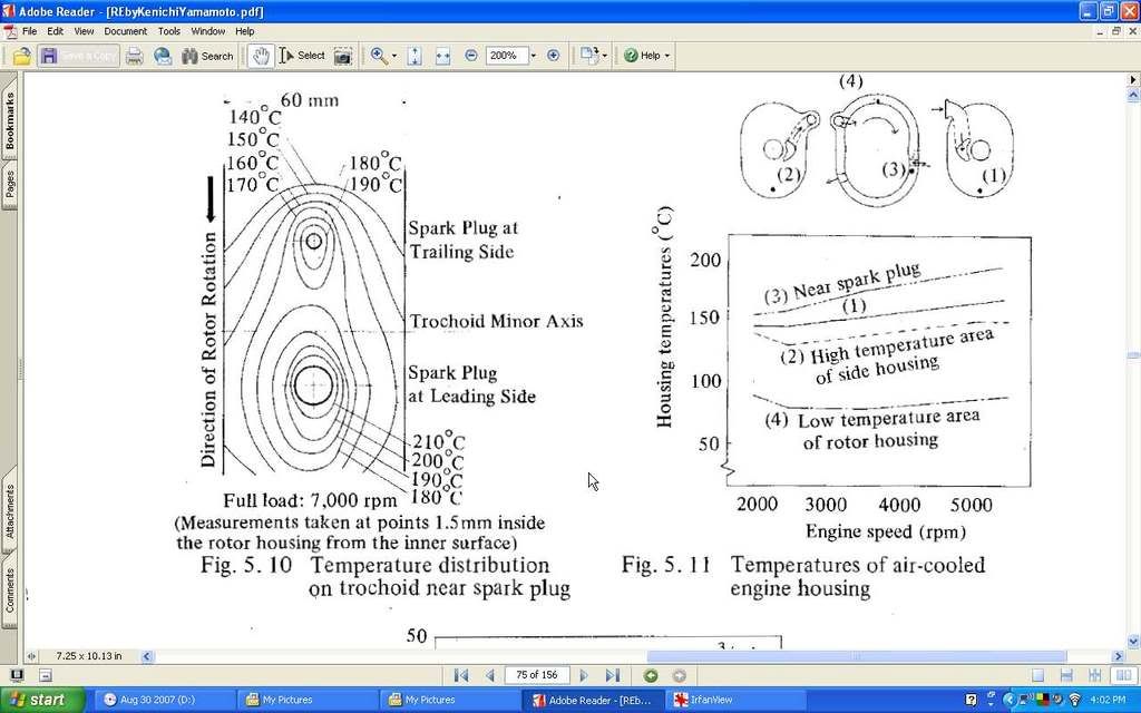
|
|
|
|
|
|
05-31-2011, 02:36 PM
|
#29 |
|
Rotary Fanatic
Join Date: Mar 2008
Posts: 123
Rep Power: 18 |
that very well could be. next time you have some used housings handy, take a straight edge and lay it across the surface, its above the spark plugs that seems to do the worst.
i did build a couple of motors with a stock diameter stud kit, and i was told to tighten it to 50lbs, but i think this is actually bad. it also certainly didn't solve the actual problem which was stock ecu/injectors with a street port and big turbo! or more correctly the owner. after thinking about it, i think the small diameter studs actually hurt more than they help. the studs DO NOT locate any of the housings any better than the stock bolts, plus #50lbs of torque the rotor housings probably ARE bowing, which is bad! mike |
|
|
|
|
05-31-2011, 08:44 PM
|
#30 |
|
RCC Loves Me Not You
Join Date: Jul 2008
Location: Influx.
Posts: 2,113
Rep Power: 20 |
So I did a little more research and I think this modified picture is quite enlightening. Sorry it's hard to make out but it's the best I can do with GIMP at the moment.
We now have flame fronts with angles of eccentric shaft and the temperatures at those flame fronts that match up with the chart. I have a few more pieces of information that I will be posting throughout the week coming from SAE paper 860560: Material Technology Development Applied to Rotary Engine at Mazda by Takumi Muroki and Jun Miyata
__________________
The Official FC Radiator Thread My Project Thread: Cerberus CCVT Virginia Rotary Group |
|
|
|
|
| Bookmarks |
|
|

 Linear Mode

