Go Back   Rotary Car Club > Tech Discussion > Rotary Tech - General Rotary Engine related tech section..

Rotary Tech - General Rotary Engine related tech section.. Tech section for general Rotary Engine... This includes, building 12As, 13Bs, 20Bs, Renesis, etc...

Reply
 
Thread Tools Display Modes
Old 07-11-2010, 05:18 AM   #31
RETed
RCC Addict
 
Join Date: Mar 2008
Location: Honolulu, Hawaii USA
Posts: 1,813
Rep Power: 19
RETed will become famous soon enough
Do we really need to turn this into a playground spat?
Can we drop the name calling?

This thread is GOLD.
Anyone who understands the data being presented knows that this kinda stuff is PRICELESS.
I think this is the first time I've seen such data on ANY RX-7 type of forum.
I've only read about stuff like this is SAE papers.
To have a member actually messing around with such equipment is just unheard of.

It would be sad if this thread gets closed.


-Ted
__________________
reted_2000@yahoo.com
Technical Advisor
FC3S Pro
http://fc3spro.com/


Quote:
Originally Posted by TitaniumTT View Post
because you're only as good as your backup
RETed is offline   Reply With Quote
Old 07-11-2010, 07:11 AM   #32
Barry Bordes
Rotary Fanatic
 
Barry Bordes's Avatar
 
Join Date: Feb 2008
Location: Slidell, LA
Posts: 191
Rep Power: 18
Barry Bordes is on a distinguished road
Quote:
Originally Posted by vex View Post
If I had to guess the pressure sensors are directly bolted in to the combustion chamber via a spark plug hole as I doubt he's using MEMS. Temperature of the combustion chamber could be taken almost directly by placing a temp sensor on the housing immediately outside of the combustion housing (ie in the coolant flow). This would allow the modeling of the temperature fairly easily, though would be rather troublesome to do.

If what I said is true then I wonder how the pressure transducers affect your readings.
Quote:
Originally Posted by RETed View Post
You'd think this would be an automatic, but this presents one problem...
This will almost always affect the spark ignition due to changing the location of the spark (plug).
It might be a minor thing, but this might throw the data off just enough...


-Ted
Quote:
Originally Posted by classicauto View Post
Yes if memory serves, Barry's sensors are the sensor/spark plug type.

This is awesome data, and could lead to some very neat results. Its just a pity that all of this data is essentially going to be setting up a bench mark being that no one's really looked at this - in the capacity of the end user - before.

Barry, have you done any comparisons yet between pressures with and without water? Can't recall if I brought that up at deals gap.....

Vex Ted and Classicauto.
Not using two plus per rotor would definitely invalidate the findings.

My third iteration spark plug is a –10 heat range TFX model, with a platinum electrode.
The only negative effect that it might have on combustion is that it is ¾” vs the Rotary designed reach of 7/8”.

Things to be tested are: with and without water, water/meth, splits, negative splits in vacuum, advance curves, port shapes, you name it.

Barry
Barry Bordes is offline   Reply With Quote
Old 07-11-2010, 07:40 AM   #33
Barry Bordes
Rotary Fanatic
 
Barry Bordes's Avatar
 
Join Date: Feb 2008
Location: Slidell, LA
Posts: 191
Rep Power: 18
Barry Bordes is on a distinguished road
Quote:
Originally Posted by NoDOHC View Post
I agree that your low pressure pulses are due to improper fuel mix at your single point of ignition (since you are using the one spark plug hole for a pressure transducer). The flame front velocity is greatly reduced in improper mix, so the flame front propogation is too slow from a weak initation event.

Two plugs per rotor are being used.

What are you using for ignition? The spark energy appears to be too low.

Twinpower, only misfires on rich fuel and heavy water/meth levels.

What is your ignition timing? Peak cycle efficiency for a piston engine is typically with peak combustion pressure occuring at 12 degrees ATDC, so I would look for 18 degrees on a rotary. It seems that your 45 degree peak pressure is running a terribly retarded ignition.
Have you tried adjusting your fuel mix to improve your combustion?

Paul Yaw quotes Yamamoto as 45º ATDC being the point of peak pressure. My tests seem to concur so far.

That is cool that you found some high speed trasducers.I have been wanting to get some for a while now, we use cylinder pressure transducers at work to maximize horsepower and efficiency, as well as emission predictions.

Area under the pressure curve is your friend (indicated torque).

Speaking of that, it is very low. I see where you mention that it is wrong. You should be seeing somewhere around 210 Lb-ft for two rotors, 105 lb-ft for a single rotor based on my output dyno findings.

Your blowdown (pressure at exhaust open) will decrease if you get your ignition timing corrected. Still this blowdown number argues for a later exhaust port opening...

You should see combustion initiation (blue and red diverge) slightly before TDC. (Not too much obviously).

Thank you so much for posting this awesome information! I really like seeing data like this.

Your peak cylinder pressure is low, but very good for 45 degrees (although that is only 30 on a piston engine). I am guessing that this is a 9.0:1 Compressiion ratio engine...

I am guessing that the sensor is in the leading plug hole, as you couldn't read pressure to the end of the power stoke in the trailing plug hole.

Correct, I need two more sensors to read full cycle. One in the exhaust port and on in the intake port (which then can test tuned lengths and overlap pressures).

I would love to drill an additional hole at the bottom of the housing to monitor so that I could observe effects of leading/trailing split.

We see both from the leading sensor location.
Barry
Barry Bordes is offline   Reply With Quote
Old 07-11-2010, 07:49 AM   #34
Barry Bordes
Rotary Fanatic
 
Barry Bordes's Avatar
 
Join Date: Feb 2008
Location: Slidell, LA
Posts: 191
Rep Power: 18
Barry Bordes is on a distinguished road
Quote:
Originally Posted by RICE RACING View Post
I asked them for a cycle to properly map a wankel rotary 1080 deg.
Have they done this Barry? without it the software is useless in my opinion. From memory when I asked this they stopped returning my E-Mail.

TFX has a Rotary model. My version is an older model but they support it well.


Can you map out one cycle at 0 to 1080 deg @ say 5000rpm for me? given where the sensor is this wont be possible sadly, to properly instrument this you would need 3 different pressure sensors equidistant machined into the rotor housing surface and all three sensors would need to be collated into each other to form one map. Me personally I don't care much for mathematical models, it would take allot to run proper sensors all over the engine (internal and other wise to get all the real information of what is happening).

Correct, I need two more sensors to read full cycle. One in the exhaust port and on in the intake port (which then can lead to more tests of tuned lengths and overlap pressures).

Still It would be good fun to play with, let us know more when you get to test it mate.
Barry
Barry Bordes is offline   Reply With Quote
Old 07-11-2010, 08:15 AM   #35
Barry Bordes
Rotary Fanatic
 
Barry Bordes's Avatar
 
Join Date: Feb 2008
Location: Slidell, LA
Posts: 191
Rep Power: 18
Barry Bordes is on a distinguished road
Quote:
Originally Posted by RICE RACING View Post
Thanks Barry,

Who do you talk to there? you can E-Mail me if you like or PM to save commentary from others, thanks.
Peter,

My contact at TFX Engine Technology is Clint Gray.

Their website has a better explanation of all the functions. http://www.tfxengine.com/index.html

Their system goes for about 5k. The plug was $1300.

All technical input is appreciated,

Barry

Last edited by Barry Bordes; 07-12-2010 at 09:44 AM.
Barry Bordes is offline   Reply With Quote
Old 07-11-2010, 10:14 AM   #36
TitaniumTT
Test Whore - Admin
 
TitaniumTT's Avatar
 
Join Date: Mar 2008
Location: Right Behind you son
Posts: 4,581
Rep Power: 10
TitaniumTT will become famous soon enough
Quote:
Originally Posted by RETed View Post
Do we really need to turn this into a playground spat?
Can we drop the name calling?

This thread is GOLD.
Anyone who understands the data being presented knows that this kinda stuff is PRICELESS.
I think this is the first time I've seen such data on ANY RX-7 type of forum.
I've only read about stuff like this is SAE papers.
To have a member actually messing around with such equipment is just unheard of.

It would be sad if this thread gets closed.


-Ted
Agreed.... 100% agreed

Quote:
Originally Posted by Barry Bordes View Post
Vex Ted and Classicauto.
Not using two plus per rotor would definitely invalidate the findings.

My third iteration spark plug is a –10 heat range TFX model, with a platinum electrode.
The only negative effect that it might have on combustion is that it is ¾” vs the Rotary designed reach of 7/8”.

Things to be tested are: with and without water, water/meth, splits, negative splits in vacuum, advance curves, port shapes, you name it.
Barry
That is just awesome
__________________
-The Angry Stig-
DGRR 2009, 2011, 2012 & 2013 - Best FC

DEALS GAP!! WOOHOOOO!!!!!

2015 Audi S4 - Samantha - Zero Brap S4
2004 RX8 - Jocelyn - 196rwhp, 19mpg fuel to noise converter
2000 Jeep Cherokee Sport - Wifey mobile - Now with 2.5" OME lift and 30" BFG AT KO's! So it begins
1998 Jeep Cherokee - 5 spd, 4" lift, 33" BFG's - Rotary Tow Vehicle
1988 'Vert - In progress
1988 FC Coupe - Gretchen -The attention whore BEAST!


I'm a sick individual, what's wrong with you?
I'm pure Evil
I'm still insane, in the best possible way.
I think Brian's idea of romance is using lube.
Your rage caused the meteor strike in Russia. The Antichrist would be proud of his minion.
You win with your thread. Most everything
It's a truck with a steel gate on the back. Just a statement of fact

Motec M820, AIM dash, ported 13B-RE Cosmo, 6-spd trans, 4.3 Torsen, custom twin wg fully divided mani, Custom 4" split into 2x 3" exhaust, Custom HMIC, Custom custom custom custom I like to welder stuff....
No Bolt-ons allowed. Dyno'ed @ Speed1 Tuned by me - 405rwhp on WG.... WM50 cuming soon.
-Angry Motherf*cker Mode ENGAGED-
TitaniumTT is offline   Reply With Quote
Old 07-11-2010, 07:53 PM   #37
NoDOHC
The quest for more torque
 
NoDOHC's Avatar
 
Join Date: Sep 2008
Location: Sheboygan, Wisconsin
Posts: 855
Rep Power: 17
NoDOHC will become famous soon enough
Sorry about the confusion, I thought the same thing that others did, this was a simple transducer installed in the leading spark plug hole.

From what I have seen, there is more available power by building that peak pressure earlier in the cycle. If you are seeing detonation with earlier pressure peaks, 45 degrees is what you get. (This really isn't too bad, at is equates to 30 degrees on a piston engine. As I recall, 12-15 degrees is the sweet spot for peak cycle efficiency (on a piston engine). The rotary may be different.

Actually, now that I think about it, the rotary has a longer combustion chamber and probably requires longer for the flame to propagate. This may mean that the pressure will spike too quickly is it is initiated any sooner, while taking too long to propagate if initiated at this time.

Anyway, I hope that you are planning to analyze the effects of leading/trailing split. Some claim that it makes a big difference, I found no change on the dyno at all for pretty much the entire test.

In fact, I unplugged the trailing plugs and saw no change under 6,000 rpm.
__________________
1986 GXL ('87 4-port NA - Haltech E8, LS2 Coils. Defined Autoworks Headers, Dual 2.5" Exhaust (Dual Superflow, dBX mufflers)
1991 Coupe (KYB AGX Shocks, Eibach lowering springs, RB exhaust, Stock and Automatic)
NoDOHC is offline   Reply With Quote
Old 07-12-2010, 05:36 AM   #38
vex
RCC Loves Me Not You
 
vex's Avatar
 
Join Date: Jul 2008
Location: Influx.
Posts: 2,113
Rep Power: 19
vex will become famous soon enough
Barry do you know your %error on the calculations at all?
vex is offline   Reply With Quote
Old 07-12-2010, 07:13 AM   #39
Barry Bordes
Rotary Fanatic
 
Barry Bordes's Avatar
 
Join Date: Feb 2008
Location: Slidell, LA
Posts: 191
Rep Power: 18
Barry Bordes is on a distinguished road
Quote:
Originally Posted by NoDOHC View Post
Sorry about the confusion, I thought the same thing that others did, this was a simple transducer installed in the leading spark plug hole.

From what I have seen, there is more available power by building that peak pressure earlier in the cycle. If you are seeing detonation with earlier pressure peaks, 45 degrees is what you get. (This really isn't too bad, at is equates to 30 degrees on a piston engine. As I recall, 12-15 degrees is the sweet spot for peak cycle efficiency (on a piston engine). The rotary may be different.

Actually, now that I think about it, the rotary has a longer combustion chamber and probably requires longer for the flame to propagate. This may mean that the pressure will spike too quickly is it is initiated any sooner, while taking too long to propagate if initiated at this time.

Anyway, I hope that you are planning to analyze the effects of leading/trailing split. Some claim that it makes a big difference, I found no change on the dyno at all for pretty much the entire test.

In fact, I unplugged the trailing plugs and saw no change under 6,000 rpm.
NoDOHC, I think flame speed should be our main focus (actually exhaust reversion is the area we can make the most gains).

There are a lot of concepts to interrelate when considering what is going on inside of a rotary engine.

This is from a Mazda paper Rotary86v6a4, Fig. 14, showing flame propagation.

I think this is probably Mazda Research at its best!

If you haven't seen it before please take your time trying to understand it.


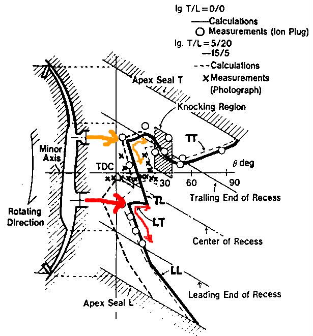
Some things to note:

Because the mixture is flowing the flame front hardly moves upstream at all. In fact the trailing portions of both flame patches are pushed backwards part of the time.

The squish generation and trench shape further complicates this movement.

When the leading and trailing flame fronts collide (at about 20º ATDC) that their speed diminishes.

The knock region is from 30º - 45º ATDC and where the knock sensor is located.

Barry
Barry Bordes is offline   Reply With Quote
Old 07-12-2010, 09:40 AM   #40
Barry Bordes
Rotary Fanatic
 
Barry Bordes's Avatar
 
Join Date: Feb 2008
Location: Slidell, LA
Posts: 191
Rep Power: 18
Barry Bordes is on a distinguished road
Quote:
Originally Posted by vex View Post
Barry do you know your %error on the calculations at all?
The sensor specs are ±1% for Combustion.
The timing trigger that I fabricated adjacent to Mazda’s timing wheel would be the area for greatest possible error.

To check this a test run is then made where the engine ignition is cut at 6000 rpm and the throttle is opened fully. This double-checks TDC in relation to the logged actual compression hump.

To my knowledge the rest are calculations.

Barry Bordes is offline   Reply With Quote
Old 07-12-2010, 09:20 PM   #41
NoDOHC
The quest for more torque
 
NoDOHC's Avatar
 
Join Date: Sep 2008
Location: Sheboygan, Wisconsin
Posts: 855
Rep Power: 17
NoDOHC will become famous soon enough
Correct me if I am completely mistaken, I will try to explain the figure.

The diagonal lines indicate the position of each component as the rotor rotates.

The angle indications are in rotor degrees, not eccentric shaft degrees.

The distance from the left indicates degrees of rotation when that region of the chamber burned.

The different lines are the different ignition timing settings that clearly cause significantly different behavior.

The trailing side seems to be the weird one, the flame front displacement seems to shift nicely for all points below the leading plug.

It looks like the flame front is traveling forward just fine, it is the backward part of the curve that confuses me. This would seem to indicate the the flame front follows the rotor rather than the housing (which makes sense, the rotor has the dish).

I think I see why it knocks right above the trailing plug, the flame front actually reverses direction there (although not relative to the rotor). This must be right at the quench boundary at the edge of the rotor dish (probably when it meets the cusp on the housing).

Do you know what the engine speed was for this test? Do you know the manifold pressure? (I would guess NA).

It appears that at 20 BTDC, the leading front has basically dissipated by 45 degrees (Eccentric shaft, 15 rotor) (which makes sense why you observed the highest pressures when the peak occured at 45 degrees)

Here is a theory about what is causing your knock on too much timing advance. Knock is typically caused by some shock wave colliding with the flame front (it can be a second flame front). My thought is that the leading and trailing sparks both touch off the mix in the chamber if the timing is advanced too far, this results in the two flame fronts colliding while they are stil moving very quickly. To test this, you could try unplugging the trailing plugs or adjusting the ignition split and observing what difference it makes.

This research is awesome. Where did you find that diagram?
__________________
1986 GXL ('87 4-port NA - Haltech E8, LS2 Coils. Defined Autoworks Headers, Dual 2.5" Exhaust (Dual Superflow, dBX mufflers)
1991 Coupe (KYB AGX Shocks, Eibach lowering springs, RB exhaust, Stock and Automatic)
NoDOHC is offline   Reply With Quote
Old 07-13-2010, 09:32 AM   #42
Barry Bordes
Rotary Fanatic
 
Barry Bordes's Avatar
 
Join Date: Feb 2008
Location: Slidell, LA
Posts: 191
Rep Power: 18
Barry Bordes is on a distinguished road
Quote:
Originally Posted by NoDOHC View Post
Correct me if I am completely mistaken, I will try to explain the figure.

The diagonal lines indicate the position of each component as the rotor rotates.

The angle indications are in rotor degrees, not eccentric shaft degrees.
I believe they are in shaft degrees.

The distance from the left indicates degrees of rotation when that region of the chamber burned.

The different lines are the different ignition timing settings that clearly cause significantly different behavior.
X is observed through a quartz window, O is taken from an ion plug, and the other two are calculated.

The trailing side (due to squish influence ) seems to be the weird one, the flame front displacement seems to shift nicely for all points below the leading plug.

It looks like the flame front is traveling forward just fine, it is the backward part of the curve that confuses me. This would seem to indicate the the flame front follows the rotor rather than the housing (which makes sense, the rotor has the dish).
We should think of the mixture flowing like a river and ignition spacing like dropping two rocks into it. Each wave travels downstream easily, upstream not so well. But what happens when the two waves collide? This interaction slows the flame speed (notice the dogleg in the LL at the bottom of the graph).

I think I see why it knocks right above the trailing plug, the flame front actually reverses direction there (although not relative to the rotor). This must be right at the quench boundary at the edge of the rotor dish (probably when it meets the cusp on the housing).

Do you know what the engine speed was for this test? Do you know the manifold pressure? (I would guess NA).
The X Measurments were done through Quarts windows NA at 1000rpm.

It appears that at 20 BTDC (ATDC?) , the leading front has basically dissipated by 45 degrees (Eccentric shaft, 15 rotor) (which makes sense why you observed the highest pressures when the peak occured at 45 degrees)


Here is a theory about what is causing your knock on too much timing advance. Knock is typically caused by some shock wave colliding with the flame front (it can be a second flame front). My thought is that the leading and trailing sparks both touch off the mix in the chamber if the timing is advanced too far, this results in the two flame fronts colliding while they are stil moving very quickly. To test this, you could try unplugging the trailing plugs or adjusting the ignition split and observing what difference it makes.

This research is awesome. Where did you find that diagram?
This is from a Mazda paper Rotary86v6a4, Fig. 14, showing flame propagation.
NoDOHC, thanks for the input.
Barry
Barry Bordes is offline   Reply With Quote
Old 07-13-2010, 10:11 PM   #43
NoDOHC
The quest for more torque
 
NoDOHC's Avatar
 
Join Date: Sep 2008
Location: Sheboygan, Wisconsin
Posts: 855
Rep Power: 17
NoDOHC will become famous soon enough
Shaft degrees makes more sense in the diagram (the rotor would have moved quit a bit further at 90 degrees). I think I was second guessing myself.

The reason I consider the ignition event to be at 20 BTDC is that there is observeable flame front propagation before 0 degrees, which excludes the ATDC option. It is strange that they neglect to indicate ATDC or BTDC.

I saw the reference earlier, I meant where did you find the paper? Is that an SAE paper?

This explains what I saw in several articles about trailing plug positioning, that further up the housing (rotor clears it earlier) is preferred for peak power.

edit: It would be really awesome to see what the flame front does at 7,000 rpm....
__________________
1986 GXL ('87 4-port NA - Haltech E8, LS2 Coils. Defined Autoworks Headers, Dual 2.5" Exhaust (Dual Superflow, dBX mufflers)
1991 Coupe (KYB AGX Shocks, Eibach lowering springs, RB exhaust, Stock and Automatic)

Last edited by NoDOHC; 07-13-2010 at 10:14 PM.
NoDOHC is offline   Reply With Quote
Old 07-14-2010, 10:17 AM   #44
vex
RCC Loves Me Not You
 
vex's Avatar
 
Join Date: Jul 2008
Location: Influx.
Posts: 2,113
Rep Power: 19
vex will become famous soon enough
Quote:
Originally Posted by Barry Bordes View Post
The sensor specs are ±1% for Combustion.
The timing trigger that I fabricated adjacent to Mazda’s timing wheel would be the area for greatest possible error.

To check this a test run is then made where the engine ignition is cut at 6000 rpm and the throttle is opened fully. This double-checks TDC in relation to the logged actual compression hump.

To my knowledge the rest are calculations.
By sensor specs for combustion do you mean the transducers? Out of curiousity how did you calibrate your transducers? Did they calibrate them for you and ship them with a cert of it (sorry for the questions, it's the engineer in me again--we've been repeatedly told "never trust some one elses calibration unless you absolutely have to"). Would I be correct in assuming the sensors are linear in nature until a certain point, or are they non-linear from min-read to max? (out of curiosity do you know what the resolution of your timing sensor is? ie: can it read only 1 degree or can it read minutes, or seconds?)

If you know the calculations they're running for any given reading you can easily perturb the uncertainties to get a culmulative percentage of error. That way you can at least know the accuracy of your results. From my glances you could be on the mark or you could be slightly off. Without the error it's hard to gage application to different stress/repeatabilty.
vex is offline   Reply With Quote
Old 07-14-2010, 05:27 PM   #45
Barry Bordes
Rotary Fanatic
 
Barry Bordes's Avatar
 
Join Date: Feb 2008
Location: Slidell, LA
Posts: 191
Rep Power: 18
Barry Bordes is on a distinguished road
Quote:
Originally Posted by vex View Post
By sensor specs for combustion do you mean the transducers? Out of curiousity how did you calibrate your transducers? Did they calibrate them for you and ship them with a cert of it (sorry for the questions, it's the engineer in me again--we've been repeatedly told "never trust some one elses calibration unless you absolutely have to"). Would I be correct in assuming the sensors are linear (yes linear) in nature until a certain point, or are they non-linear from min-read to max? (out of curiosity do you know what the resolution of your timing sensor is? ie: can it read only 1 degree or can it read minutes, or seconds?)

You realize at 360º X 8000 rpm it is taking at almost 3 million samples /min. My laptop is the restriction right now and I would like to add 2 more sensors ( for intake and exhaust ports).

If you know the calculations they're running for any given reading you can easily perturb the uncertainties to get a culmulative percentage of error. That way you can at least know the accuracy of your results. From my glances you could be on the mark or you could be slightly off. Without the error it's hard to gage application to different stress/repeatabilty.
Vex, check out this info, (Very accurate and cost effective, an interesting combination).

For aircraft testing instrumentation we had to recertify sometimes every six months. I don't want to certify different dynos for the FAA or DOT. I want it to be accurate but I will pass on recertification.

Really I just want to know is this log an improvement or have I gone too far!
I am using it just like our Datalogit tuning for AFR, transition, etc.

http://www.optrand.com/Papers/fisita98/fisita98.htm

Barry

Last edited by Barry Bordes; 07-14-2010 at 05:54 PM.
Barry Bordes is offline   Reply With Quote
Reply

Bookmarks

Tags
barry bordes, bmep, imep, in chamber, pressure sensors, tfx


Posting Rules
You may not post new threads
You may not post replies
You may not post attachments
You may not edit your posts

BB code is On
Smilies are On
[IMG] code is On
HTML code is On

Forum Jump


All times are GMT -5. The time now is 09:52 AM.


Powered by vBulletin® Version 3.8.4
Copyright ©2000 - 2025, Jelsoft Enterprises Ltd.
Hosted by www.GotPlacement.com