|
|||||||


| Rotary Tech - General Rotary Engine related tech section.. Tech section for general Rotary Engine... This includes, building 12As, 13Bs, 20Bs, Renesis, etc... |
 |
|
|
Thread Tools | Display Modes |
|
|||||||
| Rotary Tech - General Rotary Engine related tech section.. Tech section for general Rotary Engine... This includes, building 12As, 13Bs, 20Bs, Renesis, etc... |
|
|
|
Thread Tools | Display Modes |
 10-10-2009, 09:08 PM
|
#1 |
|
Rotary Fanatic

Join Date: Feb 2008
Location: Slidell, LA
Posts: 191
Rep Power: 18  |
Why Apex Seals Fail
Most people think that that their apex seal failures are caused by detonation. More specifically, they think the detonation was caused by some combination of poor fuel, advanced ignition, and high boost. This can and does happen but is not the root cause of the seal breakage.
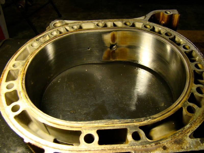
One of my engines, which I thought would run a very long time because of reliability mods and low boost (14psi), lost an apex seal at about 30K miles. The only good news was that upon close examination I discovered a second apex seal in the set that was cracked but had not yet broken. (Sorry the magnification isn't better.) 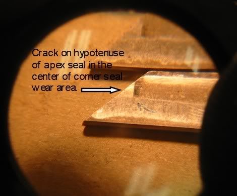 I was surprised to find crack was emanating from the bottom side not at the exposed working face! It makes perfect sense. The main part of the seal is supported unevenly at three points. The forth spring contact point is on the wedge portion of the seal. When the seal rocks over the high point in the housing, specifically, the spark plug openings, the tip is under pressure from the wedge. 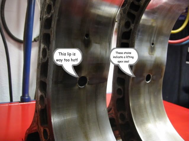
|

|

|
|
10-10-2009, 09:12 PM
|
#2 |
|
Rotary Fanatic
Join Date: Feb 2008
Location: Slidell, LA
Posts: 191
Rep Power: 18 |
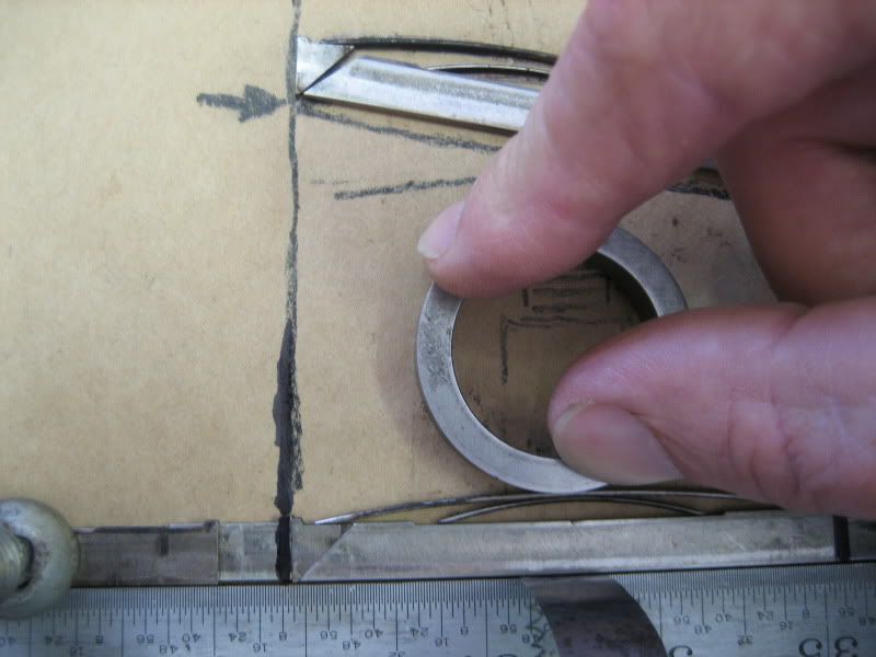
So you can try a little experiment to test this hypothesis. Install a .0015 feeler gauge at the center of the apex seal simulating the raised spark plug area. The seal will be rocked-over .003 and the wedge will put pressure on the pointed end of the apex seal. Note the exaggerated condition depicted at the top of the picture.
 But we still havent gotten to the root cause. The real problem is the raised spark plug area on the housing. There are at least three approaches to this problem: (1)- Use cold heat range plugs like NGK R7420-10 or 10.5. (This is easiest part of the solution.) (2)-The harder second part is to cool the housing better. A better pump is a good start. Second gen. cast impeller type pumps are a lot better or the Remedy pump for 3rd gens. (3)-The most difficult part would be to port the housing in the spark plug area to minimize distortion. But what is the best way? The factory racing peripheral housing have a trough cast into the inner water jacket in this area but the are for NA applications. 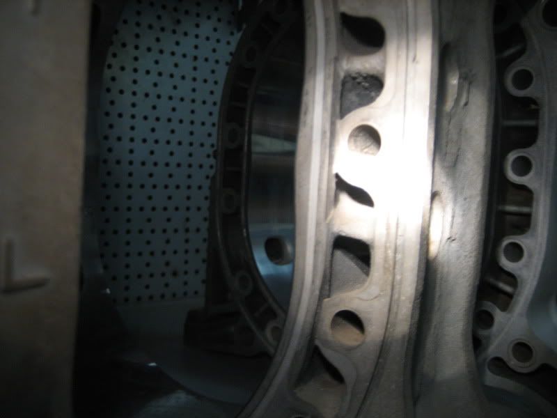 Notice that the thru-bolt bosses have been severed. |
|
|
|
|
10-10-2009, 09:13 PM
|
#3 |
|
Rotary Fanatic
Join Date: Feb 2008
Location: Slidell, LA
Posts: 191
Rep Power: 18 |
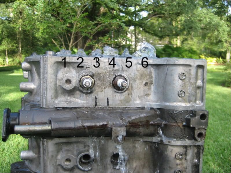 This is what a stock housing flows like. Notice we have too much flow on #6 passage below the spark plug and not enough on #5 passage. Any thoughts? Barry |
|
|
|
|
10-10-2009, 10:38 PM
|
#4 |
|
The quest for more torque

Join Date: Sep 2008
Location: Sheboygan, Wisconsin
Posts: 855
Rep Power: 18 |
Wow! This is awesome information. I have seen the same marking on several sets of housings and I never made the hot plug area connection.
It makes sense that the housings would grow the most next to the spark plug, both because there is a more extended high temperature condition in that region than elsewhere and because the housing is less restrained (threads tend to grow more than smooth holes). I have known spark plugs to gall in place on rotaries and that the plugs show signs of high combustion temperatures. I have also seen two housings where the apex seal left a large mark in the housing 1/2" to 3/4" after the leading plug hole (looked as if that was where the seal actually failed). I wonder if a very small bevel around the spark plugs would cause a significant loss of cold compression. This may save apex seals from the spark plug speed bump when under boost. Fooling with the coolant passages would be difficult, as they go through the intermediate iron and both end plates. Maybe a little porting on #5 (without getting too close to the plug). Maybe some experienced builders can give a better number on how many housings have this damage. I can add this as a good reason in the causes of rotary engine failure section once we have more information. Thanks for the input.
__________________
1986 GXL ('87 4-port NA - Haltech E8, LS2 Coils. Defined Autoworks Headers, Dual 2.5" Exhaust (Dual Superflow, dBX mufflers) 1991 Coupe (KYB AGX Shocks, Eibach lowering springs, RB exhaust, Stock and Automatic) |
|
|
|
|
10-12-2009, 03:23 PM
|
#5 |
|
The Newbie
Join Date: Jul 2009
Posts: 20
Rep Power: 0 |
that's some good info. thank you.
|
|
|
|
|
10-20-2009, 11:43 AM
|
#6 | ||
|
crash auto?fix auto

Join Date: Feb 2008
Posts: 816
Rep Power: 18 |
Quote:
The main problem is that the temperatures are so out of control in that spot that making headway to reducing them still hasn't brought them down to a level on par with the rest of the housing surface. I've tried all kinds of mods to minimize the growth there but nothing can completely manage it, yet. It only serves to reduce the severity. I've done a couple different styles of jacket mods, run a high flow (REmedey) waterpump, and use 10 and 10.5 plugs (NGK 7420). Still haven't needed to build my next engine to try the additional web or bridge or heat sink (chunk of AL inserted diagonally in the leading plug cooling passage on both sides of it) out. But I'm not exactly disappointed that I haven't needed another yet  Currently floating around my mind are the idea previously mentioned, as well as running higher system pressure. Much higher. Also, Barry pointed out some NGK surface gap style plugs which appear to perhaps retain less heat given their tip design vs. the 7420's.
__________________
Quote:
Last edited by Barry Bordes; 10-28-2009 at 10:33 AM. |
||
|
|
|
|
11-13-2009, 08:43 AM
|
#7 | |
|
Rotary Fanatic
Join Date: Feb 2008
Location: Slidell, LA
Posts: 191
Rep Power: 18 |
Quote:
This may be a problem, they may be a little large for boosted engines. Also it would be nice if they were made of some rare earth metals like platinum or iridium. Barry |
|
|
|
|
|
05-22-2011, 07:28 AM
|
#8 |
|
The quest for more torque
Join Date: Sep 2008
Location: Sheboygan, Wisconsin
Posts: 855
Rep Power: 18 |
Ok, so I have a few pictures of my own to back up Barry's Theory:
Naturally Aspirated application - 13.2:1 AFR 28 degrees BTDC Timing failed apex seal in front housing at 5400 rpm in 4th gear - after 37 seconds at WOT in road load simulation mode on Mustang dyno. This happened a while back, but my camera was acting up. Here are the Apex seals:  The housing in which the seals failed:  Another shot of the housing in which the seals failed:  Here is the other housing:  You can see that the seals failed exactly as Barry predicted.
__________________
1986 GXL ('87 4-port NA - Haltech E8, LS2 Coils. Defined Autoworks Headers, Dual 2.5" Exhaust (Dual Superflow, dBX mufflers) 1991 Coupe (KYB AGX Shocks, Eibach lowering springs, RB exhaust, Stock and Automatic) |
|
|
|
|
05-23-2011, 10:16 AM
|
#9 |
|
Rotary Fanatic
Join Date: Feb 2008
Location: Slidell, LA
Posts: 191
Rep Power: 18 |
NoDOHC, check the remaining good seal under a microscope for a crack where the others failed.
Also what water pump are you running? Did you bevel the spark plug holes? It appears that way from the pictures. Barry Last edited by Barry Bordes; 05-23-2011 at 10:19 AM. |
|
|
|
|
05-23-2011, 01:03 PM
|
#10 |
|
destroy, rebuild, repeat

Join Date: Feb 2008
Location: Charleston, SC
Posts: 395
Rep Power: 18 |
mine had the same marks:
 this was with RA classic seals, but they didnt break, it just had leaking coolant seals. it had 60k miles on stock turbo 15 psi, 7's and 9's plugs
__________________
1993 RX-7 Touring MB, stockport 13B-REW, 9.4CR rotors, T04S 60-1/p-trim single turbo 1986 RX-7 Base project track beast |
|
|
|
|
05-23-2011, 01:29 PM
|
#11 | |
|
RCC Loves Me Not You

Join Date: Jul 2008
Location: Influx.
Posts: 2,113
Rep Power: 20 |
Quote:
Let me see if I can help in adding my schooling into the mix (Hurrah for Fluid Dynamics being applicable in all situations dealing with flow). I think the ROOT cause of the flow issue is going to take some exploring. First and foremost what do the individual passages look like? I notice from the picture you appear to have a lot of, what appears to be, leakage between the sideplate and the rotor housing. If that's just an illusion then we can forego that issue. However if it's not I think a pressure differential is developing prior to the passage. What I mean by that is that if you have a single source flowing unevenly into the various passages the incompressible nature of the fluid is going to dictate that the area with the higher pressure is going to output the more mass of the fluid (all other things being equal). Consequently ensuring you're getting an equal flow rate prior to the passage entrance would be paramount. If however there is no leakage and the input is simply just feeding it through the water ports where the waterpump seals, then the issue is indeed hardware related. Consequently since we can assume a uniform pressure distribution (not only for this experiment but for the real world application) we can see that the differences is going to be directly related to the hydraulic diameter and boundary layer conditions of the passages. This provides us with an easy enough solution as well. First and foremost; enlarging the hydraulic diameter of the passages will allow for a more unified flow condition between all ports in question. There remains however a finite amount of space to achieve that. The other option that can be excersized as well would be to instill a turbulent boundary layer on only some of the passages. Why only some? Think of it this way: we have a large passage that is putting out a lot of fluid. The issue is attempting to balance the passages to output the same amount of fluid at the end of the day. To do this we can lower the friction a majority of the fluid is exposed to in the other passages, in essence allowing for a faster flow to be achieved on smaller passages, while the undisturbed boundary layer on the larger passage causes the flow to slow down when compared to the tripped boundary layer of the smaller passages. The solution will consist of finding the appropriate balance of the two.
__________________
The Official FC Radiator Thread My Project Thread: Cerberus CCVT Virginia Rotary Group |
|
|
|
|
|
05-23-2011, 01:59 PM
|
#12 |
|
Waffles - hmmm good

Join Date: Aug 2008
Location: Huntersville, NC
Posts: 757
Rep Power: 0 |
Vex it sounds like your analysis is right on. Check out what RB has been offering
for years now. Looks almost like what your describing.  They describe it here: http://www.racingbeat.com/RX7-1975-1...tem/11488.html The description talks about heat transfer being improved due to the grooves but I wonder if thats some purposeful FUD and the real solution is along the lines that your describing. It would all depend on exactly what they groove and where I guess. This is a great thread by the way.
__________________
1980 GS stockport, Fat Nikki, RB Dual Facetfuel pumps, Holley regulator, RB Street port exhaust, 2GDFIS, MR2 MK I electric fans, 2G strut bar, relayed fans, lights and fuel pump, LEDs Project Fat Nikki Budget 12A rebuild Video setup < $30.00 |
|
|
|
|
05-23-2011, 02:37 PM
|
#13 | |
|
RCC Loves Me Not You
Join Date: Jul 2008
Location: Influx.
Posts: 2,113
Rep Power: 20 |
Quote:
I know that's confusing, but it's the best I got without drawing a picture of what I mean. Infernosig (sp?) may be able to explain what I mean better.
__________________
The Official FC Radiator Thread My Project Thread: Cerberus CCVT Virginia Rotary Group |
|
|
|
|
|
05-23-2011, 02:52 PM
|
#14 |
|
Waffles - hmmm good
Join Date: Aug 2008
Location: Huntersville, NC
Posts: 757
Rep Power: 0 |
Yep, thats why I said "almost" and "it would all depend". Obviously you wouldn't
groove every opening as RB has done and I'm sure it would take some intensive R&D to optimize it. Whats interesting is there are still so many improvements that can and will be made to the rotary to make it better. Think of how many refinements and designs have been wrought on the piston engine in the last 100 years to get it where it is today. The rotary has barely been in production for 50 years so far.
__________________
1980 GS stockport, Fat Nikki, RB Dual Facetfuel pumps, Holley regulator, RB Street port exhaust, 2GDFIS, MR2 MK I electric fans, 2G strut bar, relayed fans, lights and fuel pump, LEDs Project Fat Nikki Budget 12A rebuild Video setup < $30.00 |
|
|
|
|
05-23-2011, 03:27 PM
|
#15 |
|
Rotary Fanatic
Join Date: Feb 2008
Location: Slidell, LA
Posts: 191
Rep Power: 18 |
Did you guys read the cooling mod thread?
http://www.rotarycarclub.com/rotary_...t=barry+bordes This thread, (Why Apex Seals Fail) is a peek into one of the conclusions that we came too. We are already running engines with this cooling mod plus some others surmised from this and other tests. Some think that this may be giving away too much valuable information. My thought is that it helps the whole rotary community. What I have noticed is that individuals start using the info and forget to give credit to the originators. But that is life... you do what is right anyway. Along that theme I would like to give credit to Carlos Lopez and Rick Engman for their thoughts on the subject. They are the community's Senior Rotary Advisors. Barry Last edited by Barry Bordes; 05-24-2011 at 06:29 AM. |
|
|
|
|
| Bookmarks |
|
|

 Linear Mode

