|
|||||||


| Rotary Tech - General Rotary Engine related tech section.. Tech section for general Rotary Engine... This includes, building 12As, 13Bs, 20Bs, Renesis, etc... |
 |
|
|
Thread Tools | Display Modes |
|
|||||||
| Rotary Tech - General Rotary Engine related tech section.. Tech section for general Rotary Engine... This includes, building 12As, 13Bs, 20Bs, Renesis, etc... |
|
|
|
Thread Tools | Display Modes |
|
|
 10-10-2009, 09:13 PM
|
#1 |
|
Rotary Fanatic

Join Date: Feb 2008
Location: Slidell, LA
Posts: 191
Rep Power: 18  |
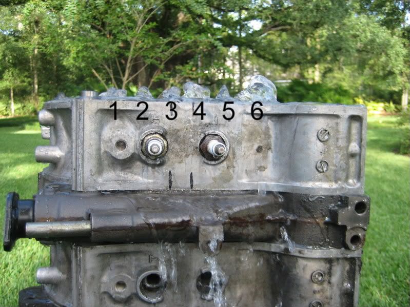 This is what a stock housing flows like. Notice we have too much flow on #6 passage below the spark plug and not enough on #5 passage. Any thoughts? Barry |

|

|
|
05-23-2011, 01:29 PM
|
#2 | |
|
RCC Loves Me Not You

Join Date: Jul 2008
Location: Influx.
Posts: 2,113
Rep Power: 20 |
Quote:
Let me see if I can help in adding my schooling into the mix (Hurrah for Fluid Dynamics being applicable in all situations dealing with flow). I think the ROOT cause of the flow issue is going to take some exploring. First and foremost what do the individual passages look like? I notice from the picture you appear to have a lot of, what appears to be, leakage between the sideplate and the rotor housing. If that's just an illusion then we can forego that issue. However if it's not I think a pressure differential is developing prior to the passage. What I mean by that is that if you have a single source flowing unevenly into the various passages the incompressible nature of the fluid is going to dictate that the area with the higher pressure is going to output the more mass of the fluid (all other things being equal). Consequently ensuring you're getting an equal flow rate prior to the passage entrance would be paramount. If however there is no leakage and the input is simply just feeding it through the water ports where the waterpump seals, then the issue is indeed hardware related. Consequently since we can assume a uniform pressure distribution (not only for this experiment but for the real world application) we can see that the differences is going to be directly related to the hydraulic diameter and boundary layer conditions of the passages. This provides us with an easy enough solution as well. First and foremost; enlarging the hydraulic diameter of the passages will allow for a more unified flow condition between all ports in question. There remains however a finite amount of space to achieve that. The other option that can be excersized as well would be to instill a turbulent boundary layer on only some of the passages. Why only some? Think of it this way: we have a large passage that is putting out a lot of fluid. The issue is attempting to balance the passages to output the same amount of fluid at the end of the day. To do this we can lower the friction a majority of the fluid is exposed to in the other passages, in essence allowing for a faster flow to be achieved on smaller passages, while the undisturbed boundary layer on the larger passage causes the flow to slow down when compared to the tripped boundary layer of the smaller passages. The solution will consist of finding the appropriate balance of the two.
__________________
The Official FC Radiator Thread My Project Thread: Cerberus CCVT Virginia Rotary Group |
|
|
|
|
|
05-23-2011, 01:59 PM
|
#3 |
|
Waffles - hmmm good

Join Date: Aug 2008
Location: Huntersville, NC
Posts: 757
Rep Power: 0 |
Vex it sounds like your analysis is right on. Check out what RB has been offering
for years now. Looks almost like what your describing.  They describe it here: http://www.racingbeat.com/RX7-1975-1...tem/11488.html The description talks about heat transfer being improved due to the grooves but I wonder if thats some purposeful FUD and the real solution is along the lines that your describing. It would all depend on exactly what they groove and where I guess. This is a great thread by the way.
__________________
1980 GS stockport, Fat Nikki, RB Dual Facetfuel pumps, Holley regulator, RB Street port exhaust, 2GDFIS, MR2 MK I electric fans, 2G strut bar, relayed fans, lights and fuel pump, LEDs Project Fat Nikki Budget 12A rebuild Video setup < $30.00 |
|
|
|
|
05-23-2011, 02:37 PM
|
#4 | |
|
RCC Loves Me Not You
Join Date: Jul 2008
Location: Influx.
Posts: 2,113
Rep Power: 20 |
Quote:
I know that's confusing, but it's the best I got without drawing a picture of what I mean. Infernosig (sp?) may be able to explain what I mean better.
__________________
The Official FC Radiator Thread My Project Thread: Cerberus CCVT Virginia Rotary Group |
|
|
|
|
|
05-23-2011, 02:52 PM
|
#5 |
|
Waffles - hmmm good
Join Date: Aug 2008
Location: Huntersville, NC
Posts: 757
Rep Power: 0 |
Yep, thats why I said "almost" and "it would all depend". Obviously you wouldn't
groove every opening as RB has done and I'm sure it would take some intensive R&D to optimize it. Whats interesting is there are still so many improvements that can and will be made to the rotary to make it better. Think of how many refinements and designs have been wrought on the piston engine in the last 100 years to get it where it is today. The rotary has barely been in production for 50 years so far.
__________________
1980 GS stockport, Fat Nikki, RB Dual Facetfuel pumps, Holley regulator, RB Street port exhaust, 2GDFIS, MR2 MK I electric fans, 2G strut bar, relayed fans, lights and fuel pump, LEDs Project Fat Nikki Budget 12A rebuild Video setup < $30.00 |
|
|
|
|
05-23-2011, 03:44 PM
|
#6 | |
|
Rotary Fanatic
Join Date: Feb 2008
Location: Slidell, LA
Posts: 191
Rep Power: 18 |
Quote:
Barry |
|
|
|
|
|
| Bookmarks |
|
|


 Hybrid Mode
