|
|||||||


| Rotary Tech - General Rotary Engine related tech section.. Tech section for general Rotary Engine... This includes, building 12As, 13Bs, 20Bs, Renesis, etc... |
 |
|
|
Thread Tools | Display Modes |
|
|||||||
| Rotary Tech - General Rotary Engine related tech section.. Tech section for general Rotary Engine... This includes, building 12As, 13Bs, 20Bs, Renesis, etc... |
|
|
|
Thread Tools | Display Modes |
 10-07-2010, 11:54 PM
|
#31 |
|
The quest for more torque

Join Date: Sep 2008
Location: Sheboygan, Wisconsin
Posts: 855
Rep Power: 18  |
Each Rotor has one intake stroke per 360 degrees of rotation.
The rotor completes 1 full revolution every 1080 degrees of eccentric shaft rotation. This is 3 intake strokes. I think this will change the dynamics.
__________________
1986 GXL ('87 4-port NA - Haltech E8, LS2 Coils. Defined Autoworks Headers, Dual 2.5" Exhaust (Dual Superflow, dBX mufflers) 1991 Coupe (KYB AGX Shocks, Eibach lowering springs, RB exhaust, Stock and Automatic) |

|

|
|
10-08-2010, 04:33 AM
|
#32 |
|
RCC Loves Me Not You

Join Date: Jul 2008
Location: Influx.
Posts: 2,113
Rep Power: 20 |
Him... I don't know then. I may have to re-evaluate the length formula, though from my understanding and checking it against the stock length on the NA version of the FC it seems to be accurate.
__________________
The Official FC Radiator Thread My Project Thread: Cerberus CCVT Virginia Rotary Group |
|
|
|
|
10-08-2010, 10:15 PM
|
#33 |
|
The quest for more torque
Join Date: Sep 2008
Location: Sheboygan, Wisconsin
Posts: 855
Rep Power: 18 |
The nice weather will soon be over. This sounds like a winter project with a notepad and a calculator. I think I loaned engine dynamic analysis book to a friend, as I can't find it anywhere. If I can find it, I will try to derive the equations for a rotary engine (from the piston engine equation derivation explanations in the book). It has been too long since I studied any of this for me to trust my memory.
I know that the rotary engine has a 298 degree intake port duration each revolution, making the airflow into the two rotors overlap (one is still filling when the other starts). This is also why the engine is so smooth, as the power strokes of the two rotors overlap. The actual maximum to minimum volume cycle of the engine occurs in 270 degrees of eccentric shaft rotation. Do you have an engine apart so that you can get a feel for what it does as it turns? I can try to get pictures, but a photographer I am not (as I think is evidenced by many of my pictures on this site). For what it's worth I think this development is very helpful to the community and I appreciate your enthusiasm and effort on the project so far. Thanks!
__________________
1986 GXL ('87 4-port NA - Haltech E8, LS2 Coils. Defined Autoworks Headers, Dual 2.5" Exhaust (Dual Superflow, dBX mufflers) 1991 Coupe (KYB AGX Shocks, Eibach lowering springs, RB exhaust, Stock and Automatic) |
|
|
|
|
10-09-2010, 02:09 PM
|
#34 | |||||
|
RCC Loves Me Not You
Join Date: Jul 2008
Location: Influx.
Posts: 2,113
Rep Power: 20 |
Quote:
Quote:
Quote:
Quote:
Quote:
In the meantime however I need to do my boundary layer theory report. 
__________________
The Official FC Radiator Thread My Project Thread: Cerberus CCVT Virginia Rotary Group |
|||||
|
|
|
|
10-09-2010, 08:54 PM
|
#35 | |
|
RCC Loves Me Not You
Join Date: Jul 2008
Location: Influx.
Posts: 2,113
Rep Power: 20 |
Of interest and the reason for using 0.0013 cubic meters:
Quote:
__________________
The Official FC Radiator Thread My Project Thread: Cerberus CCVT Virginia Rotary Group |
|
|
|
|
|
01-25-2011, 11:54 AM
|
#36 |
|
RCC Loves Me Not You
Join Date: Jul 2008
Location: Influx.
Posts: 2,113
Rep Power: 20 |
So... I figured I should update this thread.
I'm currently going through design iterations of a new intake. As it stands I have balanced the runners with plenum geometry. Some pointers to keep in mind when doing this yourself:
__________________
The Official FC Radiator Thread My Project Thread: Cerberus CCVT Virginia Rotary Group |
|
|
|
|
01-25-2011, 08:36 PM
|
#37 | |
|
The quest for more torque
Join Date: Sep 2008
Location: Sheboygan, Wisconsin
Posts: 855
Rep Power: 18 |
I should clarify a previous post. I re-read it and got confused myself.
Quote:
My apologies on the misinformation. The cool thing about the rotary engine is that although the port open time is overlap-equivalent to 2/3 the timing for a piston engine - 192 degrees for a four port (talk about a tame cam), the air has the same amount of time to enter the rotor as it would with 288 degrees of intake duration on a piston engine. Bear in mind too that well-ported ports on a rotary flow much better than an equivalent-sized valve (over 3 square inches of area between the ports would require one 2+" valve or 2 1.4+" valves). This is why the intake manifold is your biggest friend (or enemy). Thanks for all your research in this vex!
__________________
1986 GXL ('87 4-port NA - Haltech E8, LS2 Coils. Defined Autoworks Headers, Dual 2.5" Exhaust (Dual Superflow, dBX mufflers) 1991 Coupe (KYB AGX Shocks, Eibach lowering springs, RB exhaust, Stock and Automatic) |
|
|
|
|
|
02-15-2011, 03:12 PM
|
#38 |
|
RCC Loves Me Not You
Join Date: Jul 2008
Location: Influx.
Posts: 2,113
Rep Power: 20 |
Time for another update (this will be used in conjunction with the NA to Turbo sticky found in the 2nd Gen forum):
To further understand the flow distribution to each runner in a manifold one needs to consider the geometry one has chosen. Flow distributions are going to be significantly different if one chooses runners 'inline' with the throttle body as compared to a 'non-inline' manifold. A picture is worth a thousand words: for a 'non-inline' type of manifold think of this:  for a 'inline' type of manifold think of something similar to this:  Both have their pro's and con's. For most people an 'inline' style manifold is going to be just fine for what they want. However there are some things to be made aware of if you're going to be making your own. First and foremost, any changes to the stock manifold should be qualified. That is; use a CFD program to calculate how your flow is going to be affected. I'm not going to get into the nitty gritty of CFD programs or even how to run them, but suffice it to say that it's better to use one than to not (you can look up OpenFOAM for a free CFD program with a large support community--I however do not use it, so don't ask me). Once you have qualified your base design to ensure uniform airflow distribution between both the front and rear rotors look at the size of the throttle body. If you can't get the flow just right, take a close look at your intake velocity . When using a CFD program, you may notice that some of the issues you encounter come from too fast of an airflow into the manifold (if you're doing boosted applications you'll need to calculate the volumetric flow rate coming through the throttle body). There are a few ways to overcome too fast of an airflow into the manifold. First and foremost increasing the size of the throttle body will inherently slow down the flow for a better and more uniform distribution. However, just upping the throttle body may not yield desired results. One must further look at how the air is expanding into the plenum. Without getting into a lot of engineering speak and mathematics; a gradual enlarging of the effective area of the flow will slow down the flow. Such an object is called a diffuser (no we're not talking about the thing that goes under the rear bumper--though they do the same feat). Diffuser geometry is very tricky to get right. If, for instance, you enlarge the diffuser too quickly you will cause the air to separate (engineering speak: The boundary layer separates) from the wall of the diffuser causing turbulence and circulation (something we're trying to avoid at this point of the flow). If you carry on the diffuser for too long the boundary layer will begin to enlarge and separate; eventually causing circulation. This is, of course, based on the intake velocity. Slower traveling intake charge will be easier to expand than a faster moving charge. For understanding the above here are some images of 75mm 'non-inline' manifold compared to a 90mm 'non-inline' manifold. (reserved)
__________________
The Official FC Radiator Thread My Project Thread: Cerberus CCVT Virginia Rotary Group |
|
|
|
|
06-09-2011, 08:32 PM
|
#39 | |
|
eibweN ehT
Join Date: Apr 2010
Posts: 15
Rep Power: 0 |
Here's a very early beta of Vex's proposed program written in C# for ease of development.
It only accepts Vex's proposed metric values for now, but I need to verify if the values and math work correctly or not to go forward with further development.
__________________
Quote:
Last edited by blaen99; 06-09-2011 at 08:37 PM. |
|
|
|
|
|
06-09-2011, 08:55 PM
|
#40 |
|
RCC Loves Me Not You
Join Date: Jul 2008
Location: Influx.
Posts: 2,113
Rep Power: 20 |
it looks like it's outputting the same values. Here's some tests for verification:
inputs: r=0.019 rpm=6500 vol=0.0013 temp=293.15 Your output: 0.22178 m My output: 0.2218 m (Due to format truncation). r=0.019 rpm=3200 vol=0.0013 temp=293.15 yours: 0.91507 mine: 0.9151 Looks like your math is fine to me. Is there a specific error you're concerned with?
__________________
The Official FC Radiator Thread My Project Thread: Cerberus CCVT Virginia Rotary Group |
|
|
|
|
06-09-2011, 09:48 PM
|
#41 | ||
|
eibweN ehT
Join Date: Apr 2010
Posts: 15
Rep Power: 0 |
Quote:
__________________
Quote:
|
||
|
|
|
|
10-06-2012, 12:07 PM
|
#42 |
|
RCC Loves Me Not You
Join Date: Jul 2008
Location: Influx.
Posts: 2,113
Rep Power: 20 |
There's been progress on this topic; I just have not been able to get back to it in a very timely manner. As a teaser: Here is a quick and dirty of a prototype intake manifold under CFD testing. I have forgone the use of a diffuser for this run; just to ensure that if I can get a uniform flow at the entrance of the manifold I get a good flow at the runners:
Here's the initial design: 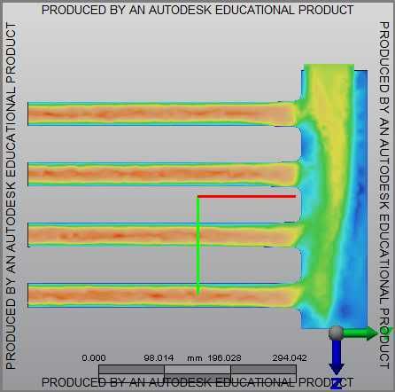 notice the poor flow distribution to the runners. This required me to alter the geometry of the plenum. Here's the final prototype: 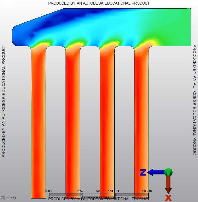
__________________
The Official FC Radiator Thread My Project Thread: Cerberus CCVT Virginia Rotary Group |
|
|
|
|
10-06-2012, 05:00 PM
|
#43 |
|
Don Mega

Join Date: Dec 2008
Location: Utopia
Posts: 1,688
Rep Power: 18 |
When I was helping a student do his Thesis (I was operating the engine dyno and doing the mapping) for SAE intake manifold runner length experiments he was tossing up to use 1st or 2nd order waves for packaging reasons.
It would be nice to use (at lesser effect) the later orders to allow a shorter more direct manifold. Have you looked into that? It's a bit like the header discussions from old people who used to race 13B P.P.'s fitted to a prototype mid engine set up. No way could you use the long header but the later order waves allowed a much shorter version and the power differences were in favor of the short through less system length and pipe friction losses. Keep up the good work.
__________________
www.riceracing.com.au Worlds best Apex Seals Coil on Plug Water Injection ECU Calibration |
|
|
|
|
10-07-2012, 04:45 AM
|
#44 | |
|
RCC Loves Me Not You
Join Date: Jul 2008
Location: Influx.
Posts: 2,113
Rep Power: 20 |
Quote:
 I have actually avoided working on the intake runner length problem for some time as I didn't have a good grasp on the physics or math of what was going on (not to mention the time I didn't really have to devote to it). I may revisit them today and better take into account the various order waves/harmonics you reference--and if I'm feeling adventurous I'll even put in pipe/friction losses. As always I'm glad to have input on matters that I don't have any experience in. As an aside I no longer have access to CFD to verify diffuser geometry or even flow distribution (as the latest update to Autodesk's suite of CFD solvers requires more resources than my little laptop can handle). I hope to remedy this situation in the coming months; but we'll see how it all plays out. Edit: Looking back over some of the Helmholtz equations for a tuned resonator I can't seem to locate any 'simple' references to what wave number enters into the calculations. Thinking over the physical process of how the intake runners work and tune I'm debating on if I need to even progress down this road. Rotarygod already did a majority of the simplification for the combined area of the stock intake runner port size. Ideally I would like to just adjust the posted forumula to account for a different runner area (combined primary and secondary ports), but if I do any more detail than that I think I would just be wasting time. Maybe I'll put this all on the back burner for awhile...
__________________
The Official FC Radiator Thread My Project Thread: Cerberus CCVT Virginia Rotary Group Last edited by vex; 10-07-2012 at 06:56 AM. |
|
|
|
|
|
01-02-2013, 07:44 PM
|
#45 |
|
Rotary Fanatic
Join Date: Mar 2008
Posts: 123
Rep Power: 18 |
neat thread! i've not much to contribute except that i've read a lot of SAE papers and Mazda has published a lot of rotary specific info.
particularly 831010 which is the 6 port intake system. the 90032 rotary P port modeling paper. also the S2000 paper is good, although isn't rotary specific. there is an S5 paper too. the crib notes, we know about the lengths, i think, shorter = higher rpm peak. they have a graph of plenum size vs VE, and due to the 270 degree cycles the rotary has what they call a tournament effect, when one rotor closes it uses the reflection to charge the other rotor. Mazda found a smaller plenum increases this effect. honda actually found the same, which is why the S2000 has a teeny plenum. with the Rx8, all the runners (primary, secondary, thirdinary, corollary, arbitrary, and fred), have tuned lengths AND diameters. from the info provided it really looks like Mazda made something that they could easily change the lengths on, and then they just tried a bunch, easier to do on a P port. mike |
|
|
|
|
| Bookmarks |
|
|

 Linear Mode

