|
|||||||


| Rotary Tech - General Rotary Engine related tech section.. Tech section for general Rotary Engine... This includes, building 12As, 13Bs, 20Bs, Renesis, etc... |
 |
|
|
Thread Tools | Display Modes |
|
|||||||
| Rotary Tech - General Rotary Engine related tech section.. Tech section for general Rotary Engine... This includes, building 12As, 13Bs, 20Bs, Renesis, etc... |
|
|
|
Thread Tools | Display Modes |
 03-01-2012, 03:03 PM
|
#1 |
|
Rotary Fanatic

Join Date: Feb 2008
Location: Slidell, LA
Posts: 191
Rep Power: 18  |
The Number One Reliability Mod for the Rotary Engine.
The Rotarys biggest flaw is the hump at the spark plug opening in the housings.
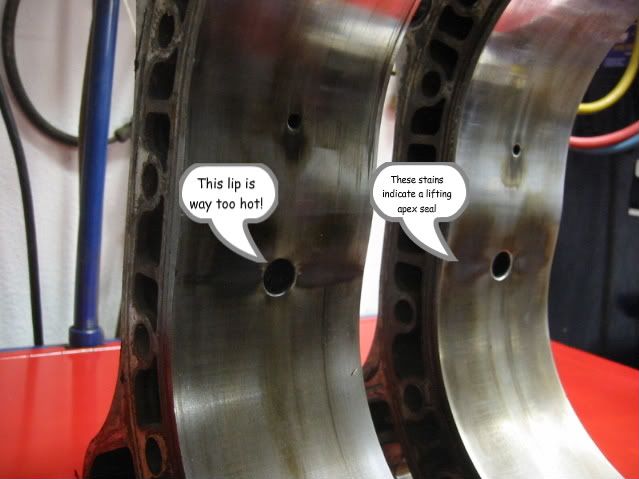 This problem area can be minimized by using cold plugs and a good water pump. But this is the Root Cause of Apex Seal problems. Hard seals chip; softer seals warp, bow, or bend. The actual problem was aggravated by a Mazda improvement. Mazda found the combustion burn-rate could be improved by widening the distance between the leading and trailing plugs. In order to do this as economically as possible they kept the through-bolt locations in the same place so they could use the existing side plates. This in turn decreases the size of probably the most important water passage in the engine! This Generational housing change is shown it the following image. 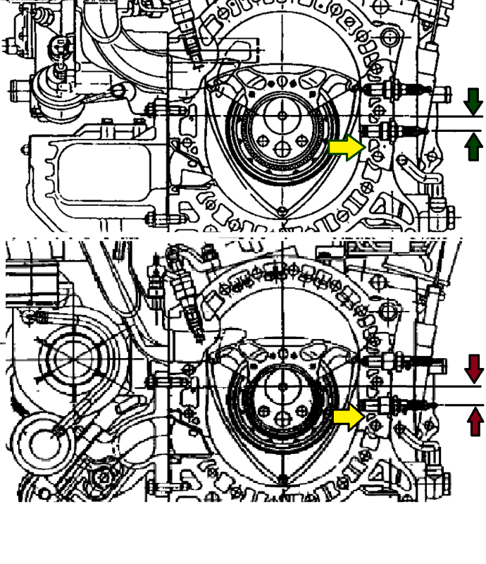 Notice that the water passages in the top housing drawing gradually get larger which corresponds to the heat map of the housing. 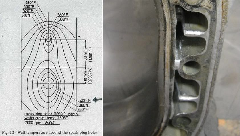 The lower drawing is of the latest version with smaller water passages on the more critical higher temp section. This is what the actual flow looks like on a 3rd housing. 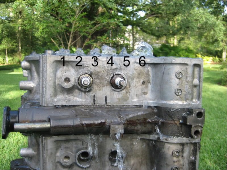 We need to increase flow at passages #3 and #5. This next shot shows the solution. The housing is ported to increase the flow at this critical area.  This is a critical area so as always a compromise must be had cutting enough to increase flow while not weakening the housing surface which supports over a 1000 psi (although over a very short period of time). Do not cut the area next the plug boss anymore than removing the casting slag. Concentrate on cutting the thru-bolt side and the floor next to the housing face. I join the 3rd gens end mill cuts from one side to the other. They are about 5mm deep. Try not to cut through boss for the thru-bolt but if you do it is not a big problem. I use a 6" long 1/4" burr. I have presented most of this information before in different threads but I thought it would be best to consolidate it as Problem/Solution , especially for new guys and home engine builders. Barry |

|

|
|
03-01-2012, 03:08 PM
|
#2 | |
|
The fan hit the shit!

Join Date: Nov 2010
Location: ocala,fl
Posts: 152
Rep Power: 16 |
I know you want to increase the flow to a extent, but if you remove too much material and speed up the flow by too much your end result would be worse than what you started with.
__________________
87 TII= High comp 13b-re,S360,Link G4 RX  Quote:
|
|
|
|
|
|
03-01-2012, 04:44 PM
|
#3 |
|
Rotary Fan in Training
Join Date: Aug 2010
Posts: 54
Rep Power: 16 |
Making the passage bigger and smooth as it appears is probably worst thing to do. At least from what I gathered about cooling principles. You want turbulent flow, very turbulent, to carry heat away. Hence the grooving on "ported" housings. Large surface is rather side effect than purpose. Otherwise just play with flow rate, this is most omitted part of whole system...
|
|
|
|
|
03-01-2012, 05:09 PM
|
#4 | |
|
I have Ultra power in me.
Join Date: Sep 2011
Posts: 457
Rep Power: 15 |
Quote:
|
|
|
|
|
|
03-01-2012, 05:30 PM
|
#5 | ||
|
The fan hit the shit!
Join Date: Nov 2010
Location: ocala,fl
Posts: 152
Rep Power: 16 |
Quote:
__________________
87 TII= High comp 13b-re,S360,Link G4 RX Quote:
|
||
|
|
|
|
03-01-2012, 07:06 PM
|
#6 |
|
The Newbie
Join Date: Mar 2010
Posts: 6
Rep Power: 0 |
Bigger passage is only a problem if you have no extra flow capacity. I seriously doubt Mazda designed the cooling system with zero extra flow capacity. Looks like Barry maybe onto something.
|
|
|
|
|
03-01-2012, 07:08 PM
|
#7 | ||
|
Half bubble off plumb

Join Date: Jan 2010
Location: middle of Alberta
Posts: 301
Rep Power: 16 |
Or increase the turbulence and the surface area... *That will aid with cooling too, or make the passage zig zag, like a Koyo n flo does (I know for this application of the coolant passages it is irrelevant, but it still stands as a proven way to extract heat, allow the medium (this case water) to a longer passage do it can be heated, or cooled...
But if the flow was increased as per the OP stated it could aid with keeping it cooler, *if the flow or quantity of medium (water) passes by it, and the medium is kept cooler due too increased flow, then it could provide cooling benefits... Although surface area is still in my opinion the greatest way to increase the cooling capacity of a system...* But then again it's been quite a while since I've ever really had to think if anything relating to physics, so I might be off my rocker.. J.
__________________
Quote:
Quote:
"The most respected cars in history are the ones which stick to their guns, do things differently and make no apologies for it." 360 gamertag: Tichlis Last edited by Prodigy; 03-01-2012 at 07:10 PM. Reason: Typed on phone, spelling errors |
||
|
|
|
|
03-01-2012, 07:43 PM
|
#8 |
|
Lifetime Rotorhead

Join Date: Apr 2010
Location: Elkton, MD
Posts: 874
Rep Power: 16 |
Interesting discussion. My first thought was that increasing the surface area, say by cutting little grooves in the coolant passages, would improve heat transfer. But I'm not a mechanical engineer, nor did I ace thermodynamics some 30 years ago when I was in school for my BSEE, so I have no idea which of the techniques discussed above (individually or in combinations) would be most effective.
Barry - were those wall temp curves something you generated yourself through testing or were they found in a reference somewhere? Would be cool if someone with an ample supply of housings, appropiate test equipment and skills could rig up a test to do a comparitive evaluation of these techniques. What I'm thinking is the housing can be installed in a test jig that allows coolant to flow through at a controlled rate. A torch or similar localized heat source to heat the area of the plug holes on the housing, which would be instrumented to measure & map the temperature distribution of heat applied. Then simultaneously measure & map coolant temps as was apparently done to generate those curves. The curves would then answer which technique or combination nets the best result. |
|
|
|
|
03-01-2012, 08:53 PM
|
#9 |
|
Test Whore - Admin

Join Date: Mar 2008
Location: Right Behind you son
Posts: 4,581
Rep Power: 10 |
I've often wanted to place a coolant temp gauge in that exact location and datalog the results.
__________________
-The Angry Stig- DGRR 2009, 2011, 2012 & 2013 - Best FC DEALS GAP!! WOOHOOOO!!!!! 2015 Audi S4 - Samantha - Zero Brap S4 2004 RX8 - Jocelyn - 196rwhp, 19mpg fuel to noise converter 2000 Jeep Cherokee Sport - Wifey mobile - Now with 2.5" OME lift and 30" BFG AT KO's! So it begins 1998 Jeep Cherokee - 5 spd, 4" lift, 33" BFG's - Rotary Tow Vehicle 1988 'Vert - In progress 1988 FC Coupe - Gretchen -The attention whore BEAST! I'm a sick individual, what's wrong with you? I'm pure Evil I'm still insane, in the best possible way. I think Brian's idea of romance is using lube. Your rage caused the meteor strike in Russia. The Antichrist would be proud of his minion. You win with your thread. Most everything It's a truck with a steel gate on the back. Just a statement of fact Motec M820, AIM dash, ported 13B-RE Cosmo, 6-spd trans, 4.3 Torsen, custom twin wg fully divided mani, Custom 4" split into 2x 3" exhaust, Custom HMIC, Custom custom custom custom I like to welder stuff.... No Bolt-ons allowed. Dyno'ed @ Speed1 Tuned by me - 405rwhp on WG.... WM50 cuming soon. -Angry Motherf*cker Mode ENGAGED- |
|
|
|
|
03-01-2012, 09:48 PM
|
#10 | |
|
My minds tellin' me no...

Join Date: Feb 2008
Location: Murfreesboro, TN
Posts: 4,043
Rep Power: 22 |
Quote:
__________________
1976 Mazda Cosmo RX-5 1976 Mazda Cosmo RX-5 2003 Toyota Tundra TRD 2015 Toyota 4Runner SR5 |
|
|
|
|
|
03-01-2012, 11:48 PM
|
#11 | ||
|
RCC Addict
Join Date: Mar 2008
Location: Honolulu, Hawaii USA
Posts: 1,813
Rep Power: 19 |
Quote:
-Ted
__________________
reted_2000@yahoo.com Technical Advisor FC3S Pro http://fc3spro.com/ Quote:
|
||
|
|
|
|
03-01-2012, 11:56 PM
|
#12 | |
|
The fan hit the shit!
Join Date: Nov 2010
Location: ocala,fl
Posts: 152
Rep Power: 16 |
I think the reason for the material increase in that are was to use it as a heatsink to pull heat away from the sparkplug area.
Barry, you don't by chance have any of the sae papers for these changes do you? I'd love to read them.
__________________
87 TII= High comp 13b-re,S360,Link G4 RX Quote:
|
|
|
|
|
|
03-02-2012, 12:09 AM
|
#13 |
|
Rotary Fanatic

Join Date: Aug 2011
Location: crockett ca.
Posts: 176
Rep Power: 0 |
Maybe it will work ,I hope it does . One way or another its still an innovative idea.
|
|
|
|
|
03-02-2012, 05:07 AM
|
#14 |
|
Don Mega

Join Date: Dec 2008
Location: Utopia
Posts: 1,688
Rep Power: 18 |
I've been building and tuning some of the worlds most powerful true street rotaries for 20+ years ......... I've never really had this "issue" personally nor seen on engines running in the upper stratosphere of power I am used to obtaining that have been tuned and set up correctly (eg, non BDC or HC tuned or built lol).
It must be more of a thing seen by people who have poor cooling systems? or *stupid* AFR settings the would over heat any engine (even at far less power). Put in a decent radiator Do proper exhaust shielding Keep water temperature at 77~78deg C Use AFR of 10.8:1 @ full load Use water injection Use Mazda Factory 2mm apex seals You wont have any of these "problems" However, I have seen these marks with brand new rotor housings using inferior after market apex seals and springs (to stock) on a few engines built by experts that I have had here after only completing run in of 600miles! (engines never been boosted or seen over 5000rpm) and power levels less than 150bhp....... much more from the apex seal not staying in contact with the rotor housing than anything to do with heat or distortion of the housing. I 100% agree with Libor, get a handle on your coolant temp and you wont have these issues, in my experience, also use stock Mazda 2mm apex seals as they are most compatible with rotor housings and actually seal far better on the rotor housing in this area especially. 
__________________
www.riceracing.com.au Worlds best Apex Seals Coil on Plug Water Injection ECU Calibration |
|
|
|
|
03-02-2012, 05:11 AM
|
#15 | |
|
RCC Addict
Join Date: Mar 2008
Location: Honolulu, Hawaii USA
Posts: 1,813
Rep Power: 19 |
Just trying to think outside the box...
How about we just drill through the rotor housing and just add an extra coolant line? I've seen this done to oiling systems on 13B's but not for the coolant system... Adding an extra coolant line into the area would: 1) add more coolant if the system can handle it, and 2) create more turbulent flow due to the "cross flow" -Ted
__________________
reted_2000@yahoo.com Technical Advisor FC3S Pro http://fc3spro.com/ Quote:
|
|
|
|
|
|
| Bookmarks |
|
|


 Linear Mode

