|
|||||||


| RX-7 2nd Gen Specific (1986-92) RX-7 1986-92 Discussion including performance modifications and technical support sections. |
 |
|
|
Thread Tools | Display Modes |
|
|||||||
| RX-7 2nd Gen Specific (1986-92) RX-7 1986-92 Discussion including performance modifications and technical support sections. |
|
|
|
Thread Tools | Display Modes |
|
|
 02-23-2017, 01:06 PM
|
#1 | |
|
Test Whore - Admin

Join Date: Mar 2008
Location: Right Behind you son
Posts: 4,581
Rep Power: 10  |
Hey Zac, remember what I said about the 7club being all fuuucocked? Well..... yeah... Check this out,,, ignore 7Dust, he was handed the answer 3 times I counted, he's a fucking stubborn idiot... I dunno what it does, so I'm gonna leave it unhooked. I don't care about idiot lights, so I;m going to leave it unhooked. There's the problem
Satch & RockLobster know what's up. It's exactly what I found out and now mine works just fine  http://www.rx7club.com/2nd-generatio...ratch-1048705/ Quote:
__________________
-The Angry Stig- DGRR 2009, 2011, 2012 & 2013 - Best FC DEALS GAP!! WOOHOOOO!!!!! 2015 Audi S4 - Samantha - Zero Brap S4 2004 RX8 - Jocelyn - 196rwhp, 19mpg fuel to noise converter 2000 Jeep Cherokee Sport - Wifey mobile - Now with 2.5" OME lift and 30" BFG AT KO's! So it begins 1998 Jeep Cherokee - 5 spd, 4" lift, 33" BFG's - Rotary Tow Vehicle 1988 'Vert - In progress 1988 FC Coupe - Gretchen -The attention whore BEAST! I'm a sick individual, what's wrong with you? I'm pure Evil I'm still insane, in the best possible way. I think Brian's idea of romance is using lube. Your rage caused the meteor strike in Russia. The Antichrist would be proud of his minion. You win with your thread. Most everything It's a truck with a steel gate on the back. Just a statement of fact Motec M820, AIM dash, ported 13B-RE Cosmo, 6-spd trans, 4.3 Torsen, custom twin wg fully divided mani, Custom 4" split into 2x 3" exhaust, Custom HMIC, Custom custom custom custom I like to welder stuff.... No Bolt-ons allowed. Dyno'ed @ Speed1 Tuned by me - 405rwhp on WG.... WM50 cuming soon. -Angry Motherf*cker Mode ENGAGED- |
|

|

|
|
02-24-2017, 12:19 AM
|
#2 |
|
RCC Loves Me Not You

Join Date: Mar 2008
Location: Eagleville, TN
Posts: 2,267
Rep Power: 20 |
Thanks Brian! That is a good explanation for me especially since I will most likely be wiring this from scratch, I'll need something for reference material. After I got off the phone with you I just couldn't go to sleep without inspecting more. Even though we were positive it doesn't contain these wires I checked an extra engine harness (passenger side) that I had laying around and it was loaded with 'T' shaped connectors so I just threw that back in the box. . . I looked for possible remains my OE two pin alternator connector by peeling back the loom on the drive side harness, still nothing. It wasn't there but what I did find was that my alternator was warm (this was after leaving that connection I made on the previous page connected for what, a couple hours?). . Looking into that, I found that I had the 'L' terminal (for dash) connected straight to battery, definitely not right.
__________________
1993 Yamaha GTS1000 1992 Celica Turbo AllTrac 1987 RX7 Sport 1979 Yamaha G1, KM24 powered 1975 Dolmar KMS4 Last edited by FC Zach; 02-24-2017 at 12:30 AM. |
|
|
|
|
02-24-2017, 12:29 AM
|
#3 | |
|
RCC Loves Me Not You
Join Date: Mar 2008
Location: Eagleville, TN
Posts: 2,267
Rep Power: 20 |
Quote:
__________________
1993 Yamaha GTS1000 1992 Celica Turbo AllTrac 1987 RX7 Sport 1979 Yamaha G1, KM24 powered 1975 Dolmar KMS4 |
|
|
|
|
|
02-25-2017, 02:37 PM
|
#4 | |
|
RCC Addict
Join Date: Mar 2008
Location: Honolulu, Hawaii USA
Posts: 1,813
Rep Power: 19 |
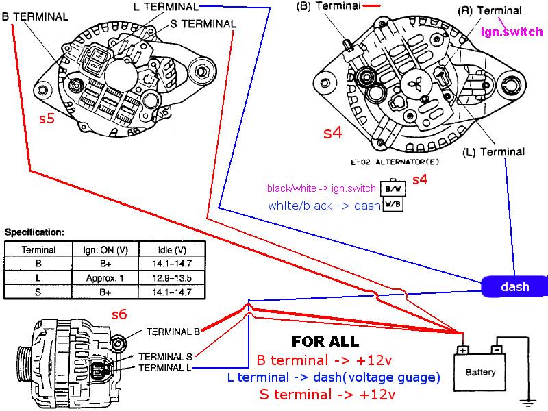
1) The 12VDC reference wire (which you call a "pin") needs to be connected to +12VDC constant, direct to the battery.
This is applicable to the FD and Kouki FC alternator circuits; prior to that, the Zenki FC alternators were only wired to switched +12VDC. This tells the alternator what the status of your battery is. Try not to connect it to the +12V post off the alternator, cause it'll be higher than the battery + post, and there's chance that you get back EMI from the alternator operation - this is why you don't see the OEM's wire it to there, even though it's a short shot. 2) The other pin is for the idiot light. Like others who have already said, it's not necessary to connect this to anything. This just completes a circuit (to ground?) so your idiots lights light up when the alternator fails. As for your problem... I had the old silverrotor FD alternator, and it always had a major drain with the engine off. I bandaided the situation by resetting my circuit breaker anytime I left the car off overnight. I traced the problem to the alternator sense field not dropping even after turning the ignition key off; for some reason when I dropped the +12V reference, this would drop the field and killed the excess current draw immediately. I just chalked it up to a crap rebuild (these things were rebuilt by silverrotor by some shop). Once I replaced with another unit, I NEVER had that problem anymore. So it's quite possible you're in a similar situation. It could be possible that you have a shorted diode in the rectifier, which would cause the alternator to keep draining voltage with the engine off too. I've fought this problem with my MX83 alternator, because I think the 15VDC+ levels my battery charger was giving it when I had to jump it. In this situation, every time you reconnected the alternator, the current draw would always be too high. It's very easy to troubleshoot these things, as you need someone to measure current - most DMM's do this. -Ted
__________________
reted_2000@yahoo.com Technical Advisor FC3S Pro http://fc3spro.com/ Quote:
Last edited by RETed; 02-25-2017 at 02:39 PM. |
|
|
|
|
|
02-25-2017, 03:21 PM
|
#5 | ||
|
RCC Loves Me Not You
Join Date: Mar 2008
Location: Eagleville, TN
Posts: 2,267
Rep Power: 20 |
Quote:
 But yeah, I am redoing the wiring now. But yeah, I am redoing the wiring now.Quote:
__________________
1993 Yamaha GTS1000 1992 Celica Turbo AllTrac 1987 RX7 Sport 1979 Yamaha G1, KM24 powered 1975 Dolmar KMS4 |
||
|
|
|
|
02-26-2017, 09:41 PM
|
#6 | |
|
RCC Loves Me Not You
Join Date: Mar 2008
Location: Eagleville, TN
Posts: 2,267
Rep Power: 20 |
Quote:

__________________
1993 Yamaha GTS1000 1992 Celica Turbo AllTrac 1987 RX7 Sport 1979 Yamaha G1, KM24 powered 1975 Dolmar KMS4 |
|
|
|
|
|
02-27-2017, 11:48 AM
|
#7 | |||||||
|
Test Whore - Admin
Join Date: Mar 2008
Location: Right Behind you son
Posts: 4,581
Rep Power: 10 |
Quote:
Regardless, in this case with Zac, he's running an FD Alt and it needs to be connected straight to the battery, not a switched source as is already there, so that is definitely problem 1 in Zac's case Quote:
Quote:
Again, I don't have the knowledge of the S4 alts just because I NEVER had a problem with mine because stock, but when I did the Cosmo swap and the S6 alt upgrade, I had issues for about 5 years... literally... because I was only running one switched wire to the alt. The death was always the same, it would start overcharging and eventually kill itself and the battery. Also, with only the one wire for the alternator connected to a key hot, when the ign switch is off, the Alt would kill the battery in a matter of days. Again, much like you, Ted, I solved that problem by flipping the breaker everytime I got out of the car - NBD Quote:
The "Sense" wire, the S wire, in the S5/6 is connected straight to the battery. It senses the voltage and adjusts the output of the alt to attempt to feed the battery the needed 14v. On the S4's it's called the R terminal, and that gets fed to the B/W wire which is hot when the key is in any position other than off. Both the "L" Terminals on the surface accomplish the same thing. They illuminate the idiot light when there is a problem. However, as far as the alt is concerned they accomplish very different things and it can be seen in the wiring diagrams. The S4 has a diode on the relay that only allows current to travel one way. When the alt goes bad, or is not charging, the W/B wire latches to ground, which energizes the coil, which closes the circuit in the relay to ground and with the other side of the idiot light connected the B/Y wire (also key hot) the light illuminates. It appears to me that the S4 alts can be run with only a single wire and run properly and as designed (meaning they won't die quickly) by leaving the idiot light wire left unhooked. Regarding the S4's, the L wire is an output, not an input as it is on the S5/6's Quote:
Quote:
 Quote:
__________________
-The Angry Stig- DGRR 2009, 2011, 2012 & 2013 - Best FC DEALS GAP!! WOOHOOOO!!!!! 2015 Audi S4 - Samantha - Zero Brap S4 2004 RX8 - Jocelyn - 196rwhp, 19mpg fuel to noise converter 2000 Jeep Cherokee Sport - Wifey mobile - Now with 2.5" OME lift and 30" BFG AT KO's! So it begins 1998 Jeep Cherokee - 5 spd, 4" lift, 33" BFG's - Rotary Tow Vehicle 1988 'Vert - In progress 1988 FC Coupe - Gretchen -The attention whore BEAST! I'm a sick individual, what's wrong with you? I'm pure Evil I'm still insane, in the best possible way. I think Brian's idea of romance is using lube. Your rage caused the meteor strike in Russia. The Antichrist would be proud of his minion. You win with your thread. Most everything It's a truck with a steel gate on the back. Just a statement of fact Motec M820, AIM dash, ported 13B-RE Cosmo, 6-spd trans, 4.3 Torsen, custom twin wg fully divided mani, Custom 4" split into 2x 3" exhaust, Custom HMIC, Custom custom custom custom I like to welder stuff.... No Bolt-ons allowed. Dyno'ed @ Speed1 Tuned by me - 405rwhp on WG.... WM50 cuming soon. -Angry Motherf*cker Mode ENGAGED- |
|||||||
|
|
|
|
02-27-2017, 02:24 PM
|
#8 | |
|
RCC Loves Me Not You
Join Date: Mar 2008
Location: Eagleville, TN
Posts: 2,267
Rep Power: 20 |
Quote:
What I'd like to do is find the old alternator wires or the connector/harness they would have come from and wire my leads there. . . wherever that is.
__________________
1993 Yamaha GTS1000 1992 Celica Turbo AllTrac 1987 RX7 Sport 1979 Yamaha G1, KM24 powered 1975 Dolmar KMS4 |
|
|
|
|
|
| Bookmarks |
|
|


 Hybrid Mode
