|
|||||||


| Rotary Tech - General Rotary Engine related tech section.. Tech section for general Rotary Engine... This includes, building 12As, 13Bs, 20Bs, Renesis, etc... |
 |
|
|
Thread Tools | Display Modes |
|
|||||||
| Rotary Tech - General Rotary Engine related tech section.. Tech section for general Rotary Engine... This includes, building 12As, 13Bs, 20Bs, Renesis, etc... |
|
|
|
Thread Tools | Display Modes |
|
|
 10-06-2012, 12:07 PM
|
#1 |
|
RCC Loves Me Not You

Join Date: Jul 2008
Location: Influx.
Posts: 2,113
Rep Power: 20  |
There's been progress on this topic; I just have not been able to get back to it in a very timely manner. As a teaser: Here is a quick and dirty of a prototype intake manifold under CFD testing. I have forgone the use of a diffuser for this run; just to ensure that if I can get a uniform flow at the entrance of the manifold I get a good flow at the runners:
Here's the initial design: 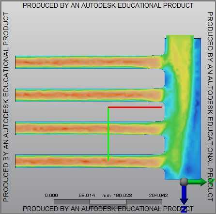 notice the poor flow distribution to the runners. This required me to alter the geometry of the plenum. Here's the final prototype: 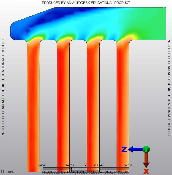
__________________
The Official FC Radiator Thread My Project Thread: Cerberus CCVT Virginia Rotary Group |

|

|
|
10-06-2012, 05:00 PM
|
#2 |
|
Don Mega

Join Date: Dec 2008
Location: Utopia
Posts: 1,688
Rep Power: 18 |
When I was helping a student do his Thesis (I was operating the engine dyno and doing the mapping) for SAE intake manifold runner length experiments he was tossing up to use 1st or 2nd order waves for packaging reasons.
It would be nice to use (at lesser effect) the later orders to allow a shorter more direct manifold. Have you looked into that? It's a bit like the header discussions from old people who used to race 13B P.P.'s fitted to a prototype mid engine set up. No way could you use the long header but the later order waves allowed a much shorter version and the power differences were in favor of the short through less system length and pipe friction losses. Keep up the good work.
__________________
www.riceracing.com.au Worlds best Apex Seals Coil on Plug Water Injection ECU Calibration |
|
|
|
|
10-07-2012, 04:45 AM
|
#3 | |
|
RCC Loves Me Not You
Join Date: Jul 2008
Location: Influx.
Posts: 2,113
Rep Power: 20 |
Quote:
 I have actually avoided working on the intake runner length problem for some time as I didn't have a good grasp on the physics or math of what was going on (not to mention the time I didn't really have to devote to it). I may revisit them today and better take into account the various order waves/harmonics you reference--and if I'm feeling adventurous I'll even put in pipe/friction losses. As always I'm glad to have input on matters that I don't have any experience in. As an aside I no longer have access to CFD to verify diffuser geometry or even flow distribution (as the latest update to Autodesk's suite of CFD solvers requires more resources than my little laptop can handle). I hope to remedy this situation in the coming months; but we'll see how it all plays out. Edit: Looking back over some of the Helmholtz equations for a tuned resonator I can't seem to locate any 'simple' references to what wave number enters into the calculations. Thinking over the physical process of how the intake runners work and tune I'm debating on if I need to even progress down this road. Rotarygod already did a majority of the simplification for the combined area of the stock intake runner port size. Ideally I would like to just adjust the posted forumula to account for a different runner area (combined primary and secondary ports), but if I do any more detail than that I think I would just be wasting time. Maybe I'll put this all on the back burner for awhile...
__________________
The Official FC Radiator Thread My Project Thread: Cerberus CCVT Virginia Rotary Group Last edited by vex; 10-07-2012 at 06:56 AM. |
|
|
|
|
|
01-02-2013, 07:44 PM
|
#4 |
|
Rotary Fanatic
Join Date: Mar 2008
Posts: 123
Rep Power: 18 |
neat thread! i've not much to contribute except that i've read a lot of SAE papers and Mazda has published a lot of rotary specific info.
particularly 831010 which is the 6 port intake system. the 90032 rotary P port modeling paper. also the S2000 paper is good, although isn't rotary specific. there is an S5 paper too. the crib notes, we know about the lengths, i think, shorter = higher rpm peak. they have a graph of plenum size vs VE, and due to the 270 degree cycles the rotary has what they call a tournament effect, when one rotor closes it uses the reflection to charge the other rotor. Mazda found a smaller plenum increases this effect. honda actually found the same, which is why the S2000 has a teeny plenum. with the Rx8, all the runners (primary, secondary, thirdinary, corollary, arbitrary, and fred), have tuned lengths AND diameters. from the info provided it really looks like Mazda made something that they could easily change the lengths on, and then they just tried a bunch, easier to do on a P port. mike |
|
|
|
|
01-13-2013, 01:52 PM
|
#5 | |
|
sumdumguy
Join Date: Nov 2012
Location: Calgary
Posts: 17
Rep Power: 0 |
Quote:
Good thread and nice work, lots of good info in here. Just a thought though, why haven't you been running your simulations with timed port openings? My brother did some similar work when designing an intake manifold for a V6. He started off modeling airflow with all valves open. The initial simulations yielded what seemed to be horrible airflow distribution:  But before we started making changes to his plenum, we decided it would be best to model the flow in as correct a manner as possible. It took a lot more work to get the time-based model working correctly, but the end results were pretty surprising. The simulation looked to be much more promising, but still not perfect - until we looked at the data from the analysis instead of the visual simulation. All runners received within 0.1% mass air volume! http://www.youtube.com/watch?v=EpJ4x...ature=youtu.be |
|
|
|
|
|
02-07-2013, 05:52 AM
|
#6 |
|
Rotary Fanatic
Join Date: Mar 2010
Location: Norway
Posts: 163
Rep Power: 16 |
What about TB placement.
From what i can find, it seems like overall runner length is the main point, and the placement of the tb isn't too important when it comes to where your powerband ends up. |
|
|
|
|
03-10-2013, 09:57 PM
|
#7 | ||||
|
RCC Loves Me Not You
Join Date: Jul 2008
Location: Influx.
Posts: 2,113
Rep Power: 20 |
Quote:
I have done some work on the Helmholtz equation, but nothing I feel comfortable sharing quite yet. Especially since wave harmonics would play a significant role in the length. Quote:
Quote:
Quote:
__________________
The Official FC Radiator Thread My Project Thread: Cerberus CCVT Virginia Rotary Group |
||||
|
|
|
|
| Bookmarks |
|
|


 Hybrid Mode
