|
|||||||


| Rotary Tech - General Rotary Engine related tech section.. Tech section for general Rotary Engine... This includes, building 12As, 13Bs, 20Bs, Renesis, etc... |
 |
|
|
Thread Tools | Display Modes |
|
|||||||
| Rotary Tech - General Rotary Engine related tech section.. Tech section for general Rotary Engine... This includes, building 12As, 13Bs, 20Bs, Renesis, etc... |
|
|
|
Thread Tools | Display Modes |
 01-13-2013, 01:52 PM
|
#46 | |
|
sumdumguy
Join Date: Nov 2012
Location: Calgary
Posts: 17
Rep Power: 0  |
Quote:
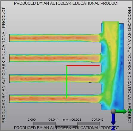
Good thread and nice work, lots of good info in here. Just a thought though, why haven't you been running your simulations with timed port openings? My brother did some similar work when designing an intake manifold for a V6. He started off modeling airflow with all valves open. The initial simulations yielded what seemed to be horrible airflow distribution:  But before we started making changes to his plenum, we decided it would be best to model the flow in as correct a manner as possible. It took a lot more work to get the time-based model working correctly, but the end results were pretty surprising. The simulation looked to be much more promising, but still not perfect - until we looked at the data from the analysis instead of the visual simulation. All runners received within 0.1% mass air volume! http://www.youtube.com/watch?v=EpJ4x...ature=youtu.be |
|

|

|
|
02-07-2013, 05:52 AM
|
#47 |
|
Rotary Fanatic
Join Date: Mar 2010
Location: Norway
Posts: 163
Rep Power: 16 |
What about TB placement.
From what i can find, it seems like overall runner length is the main point, and the placement of the tb isn't too important when it comes to where your powerband ends up. |
|
|
|
|
03-10-2013, 09:57 PM
|
#48 | ||||
|
RCC Loves Me Not You

Join Date: Jul 2008
Location: Influx.
Posts: 2,113
Rep Power: 20 |
Quote:
I have done some work on the Helmholtz equation, but nothing I feel comfortable sharing quite yet. Especially since wave harmonics would play a significant role in the length. Quote:
Quote:
Quote:
__________________
The Official FC Radiator Thread My Project Thread: Cerberus CCVT Virginia Rotary Group |
||||
|
|
|
|
03-12-2013, 05:15 PM
|
#49 |
|
RCC Loves Me Not You
Join Date: Jul 2008
Location: Influx.
Posts: 2,113
Rep Power: 20 |
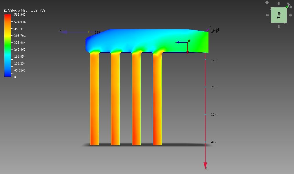
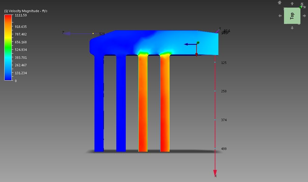
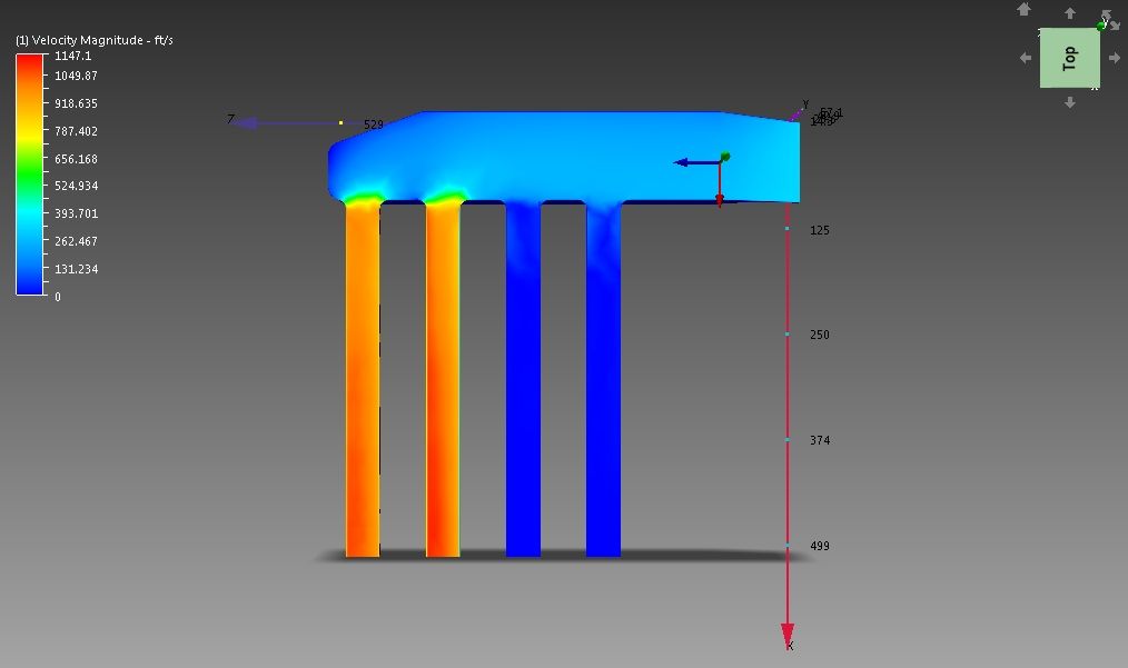
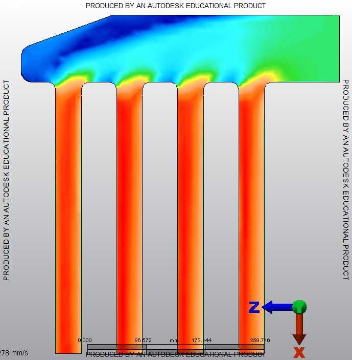
Here's some pictures without explanation.
__________________
The Official FC Radiator Thread My Project Thread: Cerberus CCVT Virginia Rotary Group |
|
|
|
|
| Bookmarks |
|
|

 Linear Mode

